
Dold 0054096 motor protection switch MK9163N.12 230V
Industrial Material > Control devices / Pilot devices > Motor protection switch
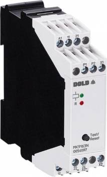
Dold 0054096 motor protection switch MK9163N.12 230V
| Lieske Part No. | 1312756 |
|---|---|
| Mfg Part No | 0054096 |
| EAN-Code | 4030641540968 |
| Manufacturer | Dold |
| Here only | 93,57 EUR
111,35 EUR incl. VAT
|
Further information for Dold 0054096 motor protection switch MK9163N.12 230V
| Technical data | |
| Auxiliary voltage | AC, AC/DC |
| Classification | Thermistor-Motorschutz |
| Enclosure design | Switch cabinet |
| Measuring range max. | > 3.8 kΩ |
| Output contacts | 2 C/O contacts |
| Width | 22,5 mm |
| Type | MK 9163N |
| Variant | |
| Contact equipping | 2 changeover contacts |
| Nominal voltage | AC 230 V |
| Terminal type | fixed terminal blocks with screw terminals |
| Approvals and Markings | UL-rec. C/US, UKCA, CCC |
| Variant | Without RESET |
Applications
The MK9163N.12 is designed for use in industrial plants where reliable temperature monitoring is required. It is particularly used in plants with high operational demands, where thermal overload can cause damage. Applications range from monitoring electric motors in production plants to temperature control in gearboxes or cooling circuits. The Gehäusebauform Schaltschrank enables mounting in standard enclosures, with a width of 22.5 mm ensuring compact placement in existing control systems.
Functions and Equipment in Detail
The device detects temperature exceedances, wire breaks in the sensor circuit, and short circuits in the sensor circuit. The pickup value is between 3.2 and 3.8 kΩ, and the drop-out value is between 1.5 and 1.8 kΩ. A fault condition is triggered when the pickup value is reached or if a sensor wire breaks. The LED indicator signals both the auxiliary voltage and the contact position, enabling quick fault localization. The output contacts consist of 2 changeover contacts, ensuring secure signal transmission. The auxiliary voltage is AC 230 V, with other voltages such as AC 110 V, AC 400 V, or DC 24 V also supported. The voltage range coverage is 0.8 to 1.1 times the nominal voltage.
Technology Explained Simply
The technology is based on measuring the resistance of connected thermistors. When a critical temperature is reached, the resistance exceeds the pickup value, triggering the relay to activate the fault condition. The measurement circuit load is under 5 mW (at 1.5 kΩ), which is very low, increasing measurement accuracy and extending the life of the thermistors. The measurement voltage is up to 2 V at a resistance of 1.5 kΩ. The turn-on delay is under 40 ms, and the turn-off delay is under 100 ms, enabling rapid response to temperature changes. The maximum bridging time during auxiliary voltage failure is 20 ms, enhancing reliability during operation.
Compatibility and Accessories
The device is designed for use with thermistors in the resistance range of 1.5 kΩ to over 3.8 kΩ. The terminal type consists of fixed terminal blocks with screw terminals, suitable for conductor cross-sections of 2 x 1.5 mm² stranded wire with ferrule and plastic sleeve, or 2 x 2.5 mm² solid (DIN 46 228-1/-2/-3/-4). The variant without reset is selected, meaning no manual reset via a button is required. The certifications UL-rec. C/US, UKCA, CCC confirm compliance with international safety standards. The device class Thermistor-Motorschutz is specified according to EN 60947-5-1 and EN 60947-8.
Mounting and Installation
Mounting is done in an enclosure, with the width of 22.5 mm enabling easy integration into standard enclosures. The terminals are designed for connection with stranded or solid conductors, with connection security ensured by the screw terminals. The terminal assignment is clearly defined, with inputs P1/P2 for the thermistors and outputs A1/A2 as well as 11-12, 11-14 for the contacts. The auxiliary voltage is supplied via A1/A2.
Advantages in Operation
The reliable temperature monitoring enables early detection of overloads, preventing damage to motors and other components. The quick fault localization via LED indicator and clear fault state signaling reduces downtime. The compact design and standard enclosure mounting simplify integration into existing plants. The long mechanical life of at least 30 million switching operations and the electrical life of 1.5 million switching operations at 4 A, AC 230 V, cosϕ = 0.6 ensure high operational reliability over a long period. Short-circuit resistance is ensured by the required fuses (6 A gG/gL for openers, 10 A gG/gL for closers).

This is an offer of:
79279 Vörstetten
https://industry-electronics.com
Tel. 07666/88499-0
Fax. 07666/88499-111
Diesen Artikel finden Sie unter:
industry-electronics.com/artikel/1312756

Lieske Elektronik e.K.
Reutener Str. 1079279 Vörstetten
https://industry-electronics.com
Tel. 07666/88499-0
Fax. 07666/88499-111
Diesen Artikel finden Sie unter:
industry-electronics.com/artikel/1312756