
Dold 0054055 time relay MK7854N.82/500 AC/DC12-240V
Industrial Material > Industrial relays and contactors > Industrial Timers
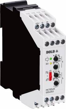
Dold 0054055 time relay MK7854N.82/500 AC/DC12-240V
| Lieske Part No. | 714369 |
|---|---|
| Mfg Part No | 0054055 |
| EAN-Code | 4030641540555 |
| Manufacturer | Dold |
| Here only | 213,31 EUR
253,84 EUR incl. VAT
|
Further information for Dold 0054055 time relay MK7854N.82/500 AC/DC12-240V
| Technical data | |
| Approvals | UL |
| Enclosure design | Switch cabinet |
| Time function(s) | Cyclic timer |
| Width | 22,5 mm |
| Type | MK 7854N |
| Connection facility for remote potentiometer | |
| Variant | |
| Contact equipping | 2 changeover contacts delayed |
| Nominal voltage | AC/DC 12 - 240 V |
| Terminal type | screw terminal fixed |
| Time range | 0,05 s - 300 h |
| Approvals and Markings | UL-listed C/US, UKCA |
| Variant | Selectable start with impulse or break. Connection facility for 2 remote for time setting |
Applications
This relay is designed for industrial applications requiring time-controlled sequences, such as in automation technology, manufacturing technology, or plant control. It is suitable for controlling drives, lighting systems, pumps, or other electrical loads that must be activated or deactivated according to a defined schedule. Control via two-wire proximity switches enables easy integration into existing systems.
Functions and Features in Detail
The device is equipped with two changeover contacts that switch with delay. The contact position and time sequence are visualized via LED indicators: a green LED indicates operational readiness, while a yellow LED shows the status of the output relay and the current time sequence (pulse or pause time). Adjustment is made via a rotary switch, with an integrated adjustment aid for quick and accurate setting of long time intervals. The blinking period of the yellow LED is 1 second ± 4 % and serves as a reference for time calibration.
Technology Explained Simply
The time control is managed by an internal timing device that executes the pre-selected pulse and pause durations. The time ranges are selectable via a rotary switch, with multiplication factors between ranges precisely defined, enabling accurate adjustment. The nominal voltage is in the range AC/DC 12 to 240 volts, ensuring broad compatibility with various supply voltages. The width is 22.5 mm, allowing compact installation in standard enclosures.
Compatibility and Accessories
The relay can be connected to two remote potentiometers to enable external time adjustment. The terminal connections are fixed screw terminals, allowing use with stranded wires with ferrules and plastic collars (2 x 1.5 mm²) or solid conductors (2 x 2.5 mm²) according to DIN 46228-1/-2/-3/-4. Control is via input A1-A2, and for operating voltages above 24 V with proximity switches lacking short-circuit protection, a series resistor is recommended to limit inrush current.
Mounting and Installation
The device is intended for mounting in enclosures and is connected via fixed screw terminals. Terminal designations are clearly defined: A1 and A2 for operating voltage, 15, 16, 18 and 25, 26, 28 for changeover contacts, B1(+) for control input to interrupt time sequence with time addition, X1/X2 for programming the second changeover contact, and Z1/Z2/Z3 for remote potentiometer connections. Mounting is carried out in the usual manner in a 22.5 mm wide enclosure.
Operational Advantages
The combination of 8 time ranges in a single device simplifies inventory management. The quick and accurate adjustment of long time intervals via the adjustment aid reduces commissioning time. The clear LED display enables easy monitoring of operational status. Control via two-wire proximity switches and the option for external time adjustment via remote potentiometers increase operational flexibility. The UL-listed C/US and UKCA certifications confirm compliance with international safety standards.
Approvals and Markings
The device is UL-listed C/US and UKCA-certified, confirming compliance with relevant safety and quality standards for industrial use. The UL approval guarantees electrical safety and reliability of the device under industrial conditions.
Housing Design and Mounting
The housing is designed for use in enclosures and offers a robust construction. The width of 22.5 mm allows compact placement in standard control panels. The fixed screw terminal ensures a secure and durable conductor connection.
Connection Options
The terminal connections are designed for various conductor cross-sections: 2 x 1.5 mm² stranded wire with ferrule and plastic collar or 2 x 2.5 mm² solid conductor according to DIN 46228-1/-2/-3/-4. Terminal designations are clearly defined, enabling unambiguous assignment of functions.
Time Functions
The time function includes the timing device function with asymmetric blinking. Pulse and pause times are independently adjustable, with time sequences visible via LED indicators. Time sequence interruption and time addition are possible via control input B1(+), providing additional operational flexibility.
Adjustment Aid
The adjustment aid uses the 1-second blinking cycle of the yellow LED to facilitate time calibration. This is particularly beneficial for long delay times, as time sequences can be simulated in a smaller range and then scaled to the desired range.
Control
Control is via input A1-A2, allowing use of both 3-wire proximity switches (for DC voltages) and 2-wire proximity switches (for AC or DC). For operating voltages above 24 V, a series resistor is recommended when using proximity switches without short-circuit protection to limit inrush current. Maximum resistor values depend on operating voltage: 270 Ω at 48 V, 390 Ω at 60 V, 680 Ω at 110 V, and 1.8 kΩ at 230 V (each 1 W).

This is an offer of:
79279 Vörstetten
https://industry-electronics.com
Tel. 07666/88499-0
Fax. 07666/88499-111
Diesen Artikel finden Sie unter:
industry-electronics.com/artikel/714369

Lieske Elektronik e.K.
Reutener Str. 1079279 Vörstetten
https://industry-electronics.com
Tel. 07666/88499-0
Fax. 07666/88499-111
Diesen Artikel finden Sie unter:
industry-electronics.com/artikel/714369