
Dold 0053944 load monitor BH9097.38/0013AC400V50/60HZ40A
Industrial Material > Industrial relays and contactors > Industrial Timers
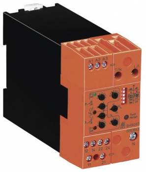
Dold 0053944 load monitor BH9097.38/0013AC400V50/60HZ40A
| Lieske Part No. | 459341 |
|---|---|
| Mfg Part No | 0053944 |
| EAN-Code | 4030641539443 |
| Manufacturer | Dold |
| Here only | 512,29 EUR
609,63 EUR incl. VAT
|
Further information for Dold 0053944 load monitor BH9097.38/0013AC400V50/60HZ40A
| Technical data | |
| 1- / 3-phase | 1, 3 |
| Enclosure design | Switch cabinet |
| Measuring range max. | 40 A (37 kW) |
| Output contacts | 2 x 1 C/O contacts |
| Width | 45 mm |
| Type | BH 9097 |
| Operate delay | |
| Variant | |
| Auxiliary voltage | Without |
| Contact equipping | 2 x 1 changeover contact |
| Nominal current max | AC 40 A |
| Nominal voltage | 3AC 400 V |
| Variant | 3-phase without auxiliary supply. Start up delay time 0 - 30 s |
Applications
The load monitor is specifically designed for monitoring industrial motors with variable load. It is suitable for applications where early detection of under- or overload conditions is critical to prevent damage to drives or machinery. The function is particularly useful in production plants, pump stations, or conveyor systems, where high operational reliability and availability are required. Adjustment is performed via rotary switches, with threshold values P1 and P2 calibrated as absolute values in watts.
Functions and Equipment in Detail
The device features two output relays, each with a 1-changeover contact, designated for signaling P1 (underload or pre-warning overload) and P2 (overload). The relays can be switched via DIP switches between operating current principle (activated in fault condition) or resting current principle (not activated in fault condition). An adjustable response delay tv suppresses short-term load fluctuations, while a common start-up bypass time ta (0–30 s) prevents false tripping during motor start-up. Configuration is performed via DIP switches, allowing selection between monitoring under- and overload (P1min/P2max) or overload only with pre-warning stage (P1max/P2max).
Technology Explained Simply
Measurement is performed according to the principle of active power measurement, with the device assuming symmetrical loading of all three phases due to its single-phase measurement principle — a condition commonly met with motor loads. Automatic range switching enables a wide measurement range without additional hardware. Indication is provided by two yellow LEDs for relay states (P1 and P2) and a green LED for mains voltage. The LEDs indicate the operating status, with flashing occurring during response delay or start-up bypass time. In case of faults, such as missing measurement voltage or reverse power, all LEDs flash in specific patterns to identify the fault.
Compatibility and Accessories
The device is configurable for 1- and 3-phase systems and complies with the standard IEC/EN 60255-1. It is designed for use in enclosures and can operate without auxiliary voltage. Wiring is reduced, as no additional sensors or transformers are required. Configuration is performed via DIP switches and rotary switches, with a test/reset button provided for commissioning and adjustment assistance. The relays are rated for a maximum load of 40 A, sufficient for many industrial drives.
Mounting and Installation
The load monitor is mounted in standard enclosures, with its width of 45 mm enabling easy placement in typical enclosure modules. Connections are made via designated terminals, with current connections (A1/A2) and voltage connections (U, T/k, L/i) clearly labeled. Adjustment of threshold values and delay times is performed on-site via rotary switches and DIP switches. The LED indicators support commissioning and fault diagnosis.
Advantages in Operation
By enabling early detection of load anomalies, the load monitor allows preventive maintenance measures that avoid costly failures. Reduced wiring and easy commissioning via test/reset button reduce installation effort. Configurability for operating or resting current principle, as well as the choice between under- and overload monitoring, increases flexibility in use. The LED indicators provide clear visual feedback on operating status and facilitate fault diagnosis.

This is an offer of:
79279 Vörstetten
https://industry-electronics.com
Tel. 07666/88499-0
Fax. 07666/88499-111
Diesen Artikel finden Sie unter:
industry-electronics.com/artikel/459341

Lieske Elektronik e.K.
Reutener Str. 1079279 Vörstetten
https://industry-electronics.com
Tel. 07666/88499-0
Fax. 07666/88499-111
Diesen Artikel finden Sie unter:
industry-electronics.com/artikel/459341