
Dold 0053814 emergency stop module BH5928.93/61 AC/DC24V
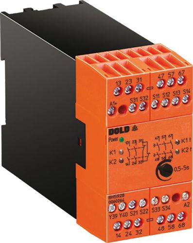
Dold 0053814 emergency stop module BH5928.93/61 AC/DC24V
| Lieske Part No. | 1001973 |
|---|---|
| Mfg Part No | 0053814 |
| EAN-Code | 4030641538149 |
| Manufacturer | Dold |
| Here only | 507,41 EUR
603,82 EUR incl. VAT
|
Further information for Dold 0053814 emergency stop module BH5928.93/61 AC/DC24V
| Technical data | |
| 1- / 2-channel | 1, 2 |
| Approvals | UL |
| Cat. / PL acc. to EN ISO 13849-1 | 4/e |
| Connection | Pluggable screw terminals |
| Output contacts max. | 3 NO contacts, 3 NO contacts delayed |
| SIL CL acc. to IEC/EN 62061 | 3 |
| SIL acc. to IEC/EN 62061 | 3 |
| Thermal current Ith max. | 5 A |
| Width | 45 mm |
| Type | BH 5928 |
| Cross fault detection | |
| Suited as safety gate monitor | |
| Variant | |
| Contact equipping | 3 NO contacts, 3 NO contacts off delay |
| Nominal voltage | AC/DC 24 V |
| Time range | 1 - 10 s |
| Approvals and Markings | UL-listed C/US, TÜV, CCC |
| Variant | With adjustable time delay |
Applications
This module is intended for use in safety-critical installations, particularly in the machine and plant construction industry. It is suitable for monitoring sliding safety grilles, which trigger an immediate shutdown of the machine when opened or when the safety zone is violated. As a safety door monitor, it can monitor the position of safety doors and trigger an emergency stop function if the safety zone is breached. The application is in systems requiring high safety integrity, such as in manufacturing automation or heavy machine tools.
Functions and Equipment in Detail
The device features a contact configuration with up to 3 normally open (NO) contacts as immediate contacts and 3 normally open (NO) contacts with delayed reset function. The time delay is adjustable and serves, for example, to enable a controlled shutdown without immediately stopping the machine. The time delay status is indicated by an LED, as well as status indicators for power supply, channel 1/2, and the delayed reset timing circuit. The connection technology uses removable screw terminals suitable for wires with 2 x 1.5 mm² (with ferrule and plastic sleeve DIN 46 228-1/-2/-3/-4) or 2 x 2.5 mm² (with ferrule DIN 46 228-1/-2/-3). Activation can be achieved via a single button connected to terminals S33-S34 or via an automatic enable function using a bridge across terminals S13-S14.
Technology Explained Simply
The safety functions of the module are based on compliance with standards and norms for safety-related controls. It meets Performance Level (PL) e and Category 4 according to EN ISO 13849-1, ensuring high safety integrity. Additionally, it meets the Safety Integrity Level (SIL) 3 requirement according to IEC/EN 62061, as well as SIL 3 according to IEC/EN 61508 and IEC/EN 61511. The cross-connection detection at the single-button input (when connected to terminals S33-S34) enables detection of incorrect wiring in the control circuit, increasing system reliability. The maximum thermal current rating is 5 A, defining the contact load capacity. The module width of 45 mm allows for compact mounting in standard control panels.
Compatibility and Accessories
The module is suitable for single- or dual-channel wiring, allowing flexible integration into various safety architectures. It is suitable as a safety door monitor and can be used in combination with appropriate safety doors or sliding safety grilles. Certifications include UL-listed C/US, TÜV, and CCC, enabling use in various markets. The terminals are removable, simplifying maintenance and installation.
Mounting and Installation
Mounting is performed in standard control panels with a width of 45 mm. The terminals are removable, simplifying wiring and maintenance. The terminals are designed for wires with 2 x 1.5 mm² (with ferrule and plastic sleeve DIN 46 228-1/-2/-3/-4) or 2 x 2.5 mm² (with ferrule DIN 46 228-1/-2/-3). Activation is either via a single button connected to S33-S34 or via an automatic enable function using a bridge across S13-S14. The status indicators (LEDs) for power supply, channel 1/2, and time delay support diagnosis and monitoring of the operational status.
Advantages in Operation
The module provides high safety integrity by meeting PL e, Category 4, and SIL 3, which is required for critical applications. The adjustable time delay enables controlled shutdown without immediately stopping the machine. Cross-connection detection increases system reliability by identifying incorrect wiring. Removable terminals and clear status indicators simplify maintenance and diagnosis. The width of 45 mm allows compact integration into existing control panels.

This is an offer of:
79279 Vörstetten
https://industry-electronics.com
Tel. 07666/88499-0
Fax. 07666/88499-111
Diesen Artikel finden Sie unter:
industry-electronics.com/artikel/1001973

Lieske Elektronik e.K.
Reutener Str. 1079279 Vörstetten
https://industry-electronics.com
Tel. 07666/88499-0
Fax. 07666/88499-111
Diesen Artikel finden Sie unter:
industry-electronics.com/artikel/1001973