
Dold 0053713 voltage relay AC25-250V
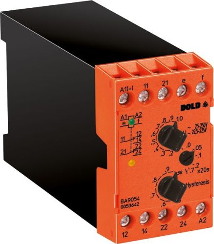
Dold 0053713 voltage relay AC25-250V
| Lieske Part No. | 1002209 |
|---|---|
| Mfg Part No | 0053713 |
| EAN-Code | 4030641537135 |
| Manufacturer | Dold |
| Here only | 325,64 EUR
387,51 EUR incl. VAT
|
Further information for Dold 0053713 voltage relay AC25-250V
| Technical data | |
| 1- / 3-phase | 1 |
| Enclosure design | Switch cabinet |
| Nominal voltage max. | AC 1000 V, DC 900 V |
| Output contacts | 2 C/O contacts |
| Width | 45 mm |
| Type | BA 9054 |
| Operate delay | |
| Variant | |
| Auxiliary voltage | AC/DC 24 - 80 V |
| Contact equipping | 2 changeover contacts |
| Measuring range | AC 25 - 250 V |
| Start up delay | Without |
| Switching delay | 0 - 20 s |
| Approvals and Markings | UKCA, CCC |
| Variant | Undervoltage relay. De-energized on trip. Time delay at hysteresis value |
Applications
This relay is designed for use in industrial plants as well as in railway applications. It monitors voltages in the range of AC 25 to 250 V and is therefore suitable for systems with medium voltage. The galvanic isolation between auxiliary circuit and measurement circuit ensures safe insulation and prevents interference in the control circuit. Monitoring is performed by measuring the arithmetic mean of the rectified voltage, with the devices calibrated for sinusoidal AC voltages in RMS value. This enables precise and reliable measurement under real operating conditions.
Functions and Equipment in Detail
The device features two changeover contacts serving as output contacts. These enable control of auxiliary circuits, for example, for switching off loads or triggering warning signals. The switching delay is 0 to 20 seconds and is activated when the hysteresis value is undershot, allowing a delayed response to short-term voltage dips. The pickup delay is also integrated to prevent unwanted activation due to transient voltage fluctuations. The auxiliary voltage can be operated in both AC and AC/DC mode with 24 to 80 V, enabling flexible integration into existing control systems.
Technology Explained Simply
Measurement is performed via terminals e and f, with the internal resistance varying depending on the measurement range. For the AC 25–250 V range, the internal resistance is 2 MΩ, ensuring high impedance and thus minimal load on the measurement circuit. The maximum permissible continuous voltage is 500 V, enabling use in networks with higher voltages. The rated voltage of the device is specified as AC 1000 V and DC 900 V, although actual measurement occurs in the range of AC 25–250 V. LED indicators signal the operating status: a green LED lights up when auxiliary voltage is applied, and a yellow LED indicates activation of the output relay.
Compatibility and Accessories
The relay is designed for use in industrial control systems and complies with standards IEC/EN 60255-1 and IEC/EN 60947-1. The UKCA and CCC certifications confirm compliance with applicable safety and quality requirements. It can be used as either an overvoltage or undervoltage relay, with hysteresis depending on the set value. The start-up bypass is not available in this variant, meaning the device becomes active immediately upon application of auxiliary voltage. The switching delay is activated when the hysteresis value is undershot, enabling controlled response to voltage dips.
Mounting and Installation
Mounting is performed in enclosures using screw terminals. The connections are clearly labeled: A1 and A2 for auxiliary voltage, e and f for the measurement circuit, and contacts 11–14 and 21–24 for the two changeover contacts. The front panel features rotary switches for setting the pickup and drop-out values, allowing device adjustment without tools. The width of 45 mm corresponds to the standard for DIN rail mounting, enabling easy integration into existing control systems.
Advantages in Operation
Early detection of voltage deviations enables preventive maintenance and prevents failures in electrical systems. Precise measurement and galvanic isolation enhance operational safety. The LED indicators provide visual feedback on the operating status, accelerating fault localization. High overload capacity and a measurement frequency up to 5 kHz ensure robust and reliable performance even under difficult operating conditions. The switching delay of 0 to 20 seconds allows differentiated response to voltage fluctuations, preventing unwanted activations during short-term disturbances.

This is an offer of:
79279 Vörstetten
https://industry-electronics.com
Tel. 07666/88499-0
Fax. 07666/88499-111
Diesen Artikel finden Sie unter:
industry-electronics.com/artikel/1002209

Lieske Elektronik e.K.
Reutener Str. 1079279 Vörstetten
https://industry-electronics.com
Tel. 07666/88499-0
Fax. 07666/88499-111
Diesen Artikel finden Sie unter:
industry-electronics.com/artikel/1002209