
Dold 0053496 undervoltage relay 230V 0,7UN4%
Industrial Material > Industrial relays and contactors > Switching units / measuring, control relay
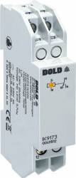
Dold 0053496 undervoltage relay 230V 0,7UN4%
| Lieske Part No. | 399232 |
|---|---|
| Mfg Part No | 0053496 |
| EAN-Code | 4030641534967 |
| Manufacturer | Dold |
| Here only | 121,00 EUR
143,99 EUR incl. VAT
|
Further information for Dold 0053496 undervoltage relay 230V 0,7UN4%
| Technical data | |
| 1- / 3-phase | 1 |
| Auxiliary voltage | Without |
| Enclosure design | Distribution board |
| Nominal voltage max. | AC 230 V, DC 125 V |
| Output contacts | 1 C/O contact |
| Width | 17,5 mm |
| Type | IK 9173 |
| Operate delay | |
| Variant | |
| Contact equipping | 1 changeover contact |
| Nominal voltage | AC 230 V |
| Response value | 0,7 Un 4% |
| Time delay | 0,5 - 20 s |
| Variant | NC circuit operation. Settable time delay t1. Fixed response value |
Applications
This relay is suitable for use in industrial and railway applications, particularly in systems requiring high operational safety and availability. It can be used for automatic switching to a safety power supply or safety lighting in accordance with DIN VDE 0100-710 or DIN VDE 0108. In unstable power networks, for example with local power generation or in networks of the 2nd and 3rd world, the variant with time delay t2 enables staged re-starting of consumers after a power failure. This is particularly important for systems such as compressors or machining machines, which must not be switched on immediately after a short interruption.
Functions and Equipment in Detail
The device features an adjustable pickup value of 0.7 times nominal voltage with a hysteresis of approximately 4 %. The time delay t1 for fault indication is adjustable between 0.5 and 20 seconds and is only effective as long as the phase voltage L-N is at least 0.5 times nominal voltage. The contact configuration includes a changeover contact (11-12-14), consisting of a normally closed contact (11-12) and a normally open contact (11-14). The contact materials are made of AgNi, ensuring high switching durability and long service life. The rated operating voltage is AC 250 V, and the thermal current Ith is 4 A. The electrical life expectancy is at least 300,000 switching operations at AC 230 V and 1 A (cos ϕ = 0.5).
Technology Explained Simply
Measurement is performed via inputs L and N, where the arithmetic mean of the voltage L-N is detected. The response time of the input circuit during phase failure is approximately 100 ms. The LED indicator lights yellow when the output relay is activated (contact 11-14 closed). The nominal voltage is AC 230 V, and the maximum nominal voltage is AC 230 V and DC 125 V. The frequency range covers 45 to 65 Hz. The device is certified to IEC/EN 60255-1, confirming compliance with international standards for measuring and protection devices.
Compatibility and Accessories
The relay is designed for installation and industrial distributors in accordance with DIN 43880. The housing design is intended for installation distributors, with a width of 17.5 mm and a depth of 59 mm. The connection terminals are arranged at the bottom. It is compatible with other devices in the VARIMETER series, particularly the SK 9173 variant, which features a greater depth and top-mounted connection terminals for enclosures with mounting plates and cable ducts.
Mounting and Installation
Mounting is performed in standard installation distributors or industrial distributors according to DIN 43880. The width of 17.5 mm allows for compact placement in distributors. The connection terminals are designed for direct connection to cables. Installation does not require additional auxiliary voltage, simplifying wiring.
Advantages in Operation
Early detection of undervoltages enables preventive maintenance and prevents costly damage. The high availability and operational safety of the system are ensured by the reliable function of the relay. The adjustable time delay t1 allows for tailored response to network disturbances, while the 4 % hysteresis ensures stable switching behavior. The LED indicator provides a visual status overview of the output relay contact position.

This is an offer of:
79279 Vörstetten
https://industry-electronics.com
Tel. 07666/88499-0
Fax. 07666/88499-111
Diesen Artikel finden Sie unter:
industry-electronics.com/artikel/399232

Lieske Elektronik e.K.
Reutener Str. 1079279 Vörstetten
https://industry-electronics.com
Tel. 07666/88499-0
Fax. 07666/88499-111
Diesen Artikel finden Sie unter:
industry-electronics.com/artikel/399232