
Dold 0053118 current relay BA9053/010 AC0,1-1A AC240V 0-20S
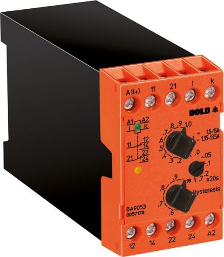
Dold 0053118 current relay BA9053/010 AC0,1-1A AC240V 0-20S
| Lieske Part No. | 1153572 |
|---|---|
| Mfg Part No | 0053118 |
| EAN-Code | 4030641531188 |
| Manufacturer | Dold |
| Here only | 255,64 EUR
304,21 EUR incl. VAT
|
Further information for Dold 0053118 current relay BA9053/010 AC0,1-1A AC240V 0-20S
| Technical data | |
| 1- / 3-phase | 1 |
| Enclosure design | Switch cabinet |
| Output contacts | 2 C/O contacts |
| Width | 45 mm |
| Type | BA 9053 |
| Operate delay | |
| Variant | |
| Auxiliary voltage | AC 240 V |
| Contact equipping | 2 changeover contacts |
| Measuring range | AC 0,1 - 1 A |
| Start up delay | Without |
| Switching delay | 0 - 20 s |
| Approvals and Markings | UKCA |
| Variant | Overcurrent relay. Energized on trip. Time delay at response value |
Applications
The relay is suitable for monitoring the current consumption of electrical loads in industrial and railway applications. It can be used both as an overcurrent relay and as an undercurrent relay, with the function determined by the threshold settings. Galvanic isolation between the auxiliary circuit and the measurement circuit ensures safe and interference-free measurement, even in electrically harsh environments. The device is installed in enclosures, with a width of 45 mm enabling compact mounting in standard control panels.
Functions and Equipment in Detail
The device features 2 changeover contacts as output contacts, which can be used to control auxiliary circuits or alarm systems. The switching delay ranges from 0 to 20 seconds and is activated once the set threshold is exceeded. This delay prevents false alarms caused by short-term current surges. The response delay is also integrated, ensuring stable reaction to gradual current changes. Measurement is performed using the arithmetic mean of the rectified measurement current, with the devices calibrated for sinusoidal AC currents in RMS value. The setting of the pickup and dropout values is done via rotary switches, with hysteresis dependent on the set value.
Technology Explained Simply
The relay measures current via an internal shunt resistor and responds when the current exceeds the set value. The auxiliary voltage is AC 240 V, connected via terminals A1 and A2. Measurement terminals i and k are used for current monitoring. The LED indicator signals operational readiness (green LED) and activation of the output relay (yellow LED). The maximum measurement frequency is 5 kHz, enabling use in systems with high dynamic requirements. The maximum overload capacity is rated for short durations up to 100 seconds (off) and 3 seconds (on), with exact values varying depending on the measurement range.
Compatibility and Accessories
The relay is designed for use in single-phase systems and can be combined with other VARIMETER models. Galvanic isolation between the auxiliary and measurement circuits enables safe integration into existing installations. The devices comply with IEC/EN 60255-1 and IEC/EN 60947-1 standards. The UKCA approval is available for the relevant variant. The start-up bypass feature is not included in this variant, so no special start-up current suppression is provided.
Mounting and Installation
Mounting is performed in enclosures using screw fastening. The width of 45 mm corresponds to the standard for DIN rail mounting. Connection terminals are clearly labeled: A1/A2 for auxiliary voltage, i/k for measurement current, and contacts 11-14 and 21-24 for the two changeover contacts. Settings are adjusted via rotary switches on the front panel, with values in the measurement range of AC 0.1 to 1 A. The devices are designed for industrial environments and require no special mounting tools.
Operational Advantages
Precise and reliable current monitoring enables faster fault localization and reduces downtime. The integrated switching delay prevents false alarms during short-term load peaks. The LED indicator provides a quick visual overview of the operating status. Galvanic isolation and high overload capacity enhance device safety and lifespan. Compliance with IEC/EN 60255-1 and IEC/EN 60947-1 standards ensures adherence to international requirements.

This is an offer of:
79279 Vörstetten
https://industry-electronics.com
Tel. 07666/88499-0
Fax. 07666/88499-111
Diesen Artikel finden Sie unter:
industry-electronics.com/artikel/1153572

Lieske Elektronik e.K.
Reutener Str. 1079279 Vörstetten
https://industry-electronics.com
Tel. 07666/88499-0
Fax. 07666/88499-111
Diesen Artikel finden Sie unter:
industry-electronics.com/artikel/1153572