
Dold 0053080 undervoltage relay 3AC500V
Industrial Material > Industrial relays and contactors > Switching units / measuring, control relay
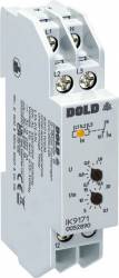
Dold 0053080 undervoltage relay 3AC500V
| Lieske Part No. | 612672 |
|---|---|
| Mfg Part No | 0053080 |
| EAN-Code | 4030641530808 |
| Manufacturer | Dold |
| Here only | 116,97 EUR
139,19 EUR incl. VAT
|
Further information for Dold 0053080 undervoltage relay 3AC500V
| Technical data | |
| 1- / 3-phase | 1, 3 |
| Auxiliary voltage | Without |
| Enclosure design | Distribution board |
| Nominal voltage max. | 3/N AC 500 / 290 V |
| Output contacts | 1 C/O contact |
| Width | 17,5 mm |
| Type | IK 9171 |
| Operate delay | |
| Variant | |
| Contact equipping | 1 changeover contact |
| Nominal voltage | 3AC 500 V |
| Response value | 0,55 - 1,05 Un 4% |
| Time delay | 0,5 - 20 s |
| Approvals and Markings | UKCA |
| Variant | Without N. NC circuit operation. Settable time delay t1. Settable response value |
Applications
This relay is used in systems where continuous voltage monitoring is required to activate protective measures in the event of voltage dips or phase failures. Typical applications include monitoring power supplies in production plants, lighting systems, or safety functions where immediate switching off or switching to a backup supply is necessary. It is particularly suitable for unstable networks, for example, in local power generation or in networks of the 2nd and 3rd world, where targeted delay times for switching off and switching on consumers are beneficial.
Functions and equipment in detail
The device detects undervoltages in three-phase networks and can also be connected single-phase. The pickup values range between 0.55 and 1.05 times the nominal voltage (Un), with a hysteresis of approximately 4 %. The time delay t1 for fault indication is adjustable and ranges from 0.5 to 20 seconds. The contact configuration includes one changeover contact (1 C/O contact), which can be used for controlling auxiliary functions or switching operations. A yellow LED indicates the status of the output relay – it lights up when contact 11-14 is closed.
Technology explained simply
Measurement is performed via the arithmetic mean of the phase voltages. In variants without neutral conductor connection, L1 and L3 are measured against L2 (IK/SK 9171). In single-phase operation, terminals L1, L2, and L3 must be connected. The time delay t1 is only effective if the phase voltage L1-N (in IK/SK 9171) is at least 0.5 times the nominal voltage. After switching on the operating voltage, the device initially enters the good state, even if a fault is present. The fault state is only activated after the time delay t1 has elapsed. This prevents unwanted false alarms during brief voltage dips.
Compatibility and accessories
The relay is designed for a nominal voltage of 3AC 500 V and can also be used in 3/N AC 50ron/290 V networks. It is suitable for frequencies between 45 and 65 Hz. The device variant without neutral conductor connection is designed for applications where no neutral conductor is available. The version without auxiliary voltage enables simple installation, as no additional supply voltage is required. The form type I (installation distributor) with a depth of 59 mm and bottom-mounted terminals is intended for standard distributor enclosures.
Mounting and installation
The device is mounted in installation and industrial distributors according to DIN 43 880. The terminals are located at the bottom, enabling easy integration into existing control systems. The width of 17.5 mm allows for compact placement in distributors. Mounting is done by inserting into the appropriate rail or mounting plate.
Advantages in operation
The relay provides reliable and low-maintenance monitoring of three-phase networks. The adjustable pickup values and time delays allow application-specific adaptation. The LED indicator facilitates visual inspection of the operating status. The rest current principle ensures that the output relay is not activated in the event of a fault, providing safe and stable operation. Compatibility with various network voltages and frequencies increases the device's versatility.

This is an offer of:
79279 Vörstetten
https://industry-electronics.com
Tel. 07666/88499-0
Fax. 07666/88499-111
Diesen Artikel finden Sie unter:
industry-electronics.com/artikel/612672

Lieske Elektronik e.K.
Reutener Str. 1079279 Vörstetten
https://industry-electronics.com
Tel. 07666/88499-0
Fax. 07666/88499-111
Diesen Artikel finden Sie unter:
industry-electronics.com/artikel/612672