
Dold 0051283 BA9019 3AC50/60HZ 200-480V 5,5KW soft starter
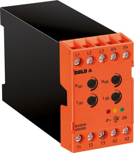
Dold 0051283 BA9019 3AC50/60HZ 200-480V 5,5KW soft starter
| Lieske Part No. | 100210 |
|---|---|
| Mfg Part No | 0051283 |
| EAN-Code | 4030641512835 |
| Manufacturer | Dold |
| Here only | 443,82 EUR
528,15 EUR incl. VAT
|
Further information for Dold 0051283 BA9019 3AC50/60HZ 200-480V 5,5KW soft starter
| Technical data | |
| Extra functions | Temperature monitoring |
| For three-phase motors, 400 V up to | 5,5 kW |
| Load voltage up to | 3AC 460 V |
| Width | 45 mm |
| Type | BA 9019 |
| Auxiliary voltage required | |
| Variant | |
| Mains / motor voltage | 3AC 200 - 480 V |
| Nominal motor power | 5,5 kW |
Applications
The device is designed for industrial applications where a gentle start and stop are required to minimize mechanical stress. Typical applications include conveyor systems, pump and fan drives, as well as machinery in the packaging industry or woodworking. The integrated soft stop function extends the natural coast-down time of the motor to avoid abrupt shutdown and associated mechanical stress. The device is used in systems requiring controlled energy transfer to prevent material damage or wear on mechanical components.
Functions and Equipment in Detail
The BA9019 features a two-phase motor control, where the power supply to two phases is controlled via alternistors. The third phase is connected directly, enabling simple and reliable control. The start and stop torque (start voltage 50–80 %, stop voltage 30–80 %) are adjustable to adapt drive dynamics to the respective load. After start-up, the semiconductors are bypassed to minimize power losses in the device. The temperature monitoring supervises internal operation and protects the device from overheating. Operation status is indicated by LEDs: green LED indicates that auxiliary voltage is present; yellow LED lights up when semiconductors are bypassed; red LED signals an activated temperature monitoring.
Technology Explained Simply
Control is performed via a galvanically isolated DC control input (X1/X2), operated with a voltage of 0 to 28.8 V DC. A start is triggered by a voltage above 13 V DC, and a stop by a voltage below 5 V DC. The auxiliary voltage (A1/A2) is DC 24 V ± 20 % and is required for device operation. The power consumption is 3 W, and the ripple content is maximum 5 %. The device is designed for continuous operation and functions in a temperature range of 0 to +55 °C. At operating altitudes above 1000 m, the maximum operating temperature decreases by 0.5 °C per 100 m. Storage is possible in the range of -25 to +75 °C. The rated insulation voltage is AC 300 V, and the overvoltage category is defined according to standards.
Compatibility and Accessories
The device complies with IEC/EN 60947-4-2 and is suitable for use in industrial control systems. It is designed for motors with a rated power of 5.5 kW at 400 V supply voltage, with maximum power reduced to 2.2 kW at 200 V. Rated currents are 8 A (3 kW) and 12 A (5.5 kW). Switching frequency is 20/h (3 kW) or 10/h (5.5 kW) at 3 times rated current and 5 seconds switching time. Protection is provided according to assignment type 1 (gG 32 A) or assignment type 2 (semiconductor fuse max. 610 A/2 s, e.g. A60Q30-2). The re-availability time is 200 ms.
Mounting and Installation
The device has a construction width of 45 mm and is intended for mounting in standard control panels. The connection terminals are clearly labeled: L1/L2/L3 for supply voltage, T1/T2/T3 for motor, A1/A2 for auxiliary voltage, and X1/X2 for control input. Installation must follow technical data and requirements of standard IEC/EN 60947-4-2. Wiring must account for galvanic isolation of control input and auxiliary voltage.
Operational Advantages
The gentle start and stop significantly reduce mechanical stress on drive components, increasing machine service life and extending maintenance intervals. Integrated temperature monitoring protects the device from overheating. Separate adjustment of start and stop parameters allows optimal adaptation to different load profiles. Galvanic isolation of control input and auxiliary voltage enhances safety and immunity to interference. The compact design with 45 mm width enables space-saving installation in control panels.
Standards and Approvals
The device complies with standard IEC/EN 60947-4-2 and is suitable for use in industrial control systems. Approvals include requirements for electronic motor control devices, including protection functions, operational safety, and electrical insulation. The overvoltage category is defined according to technical specifications.
Connection and Operation
The operating voltage is in the range of 3AC 200–480 V, and the load voltage is up to 3AC 460 V. The auxiliary voltage (A1/A2) must be DC 24 V ± 20 %. Control is performed via the DC input X1/X2, where start is triggered by voltage >13 V DC and stop by voltage <5 V DC. Status is indicated by LEDs, visually signaling the operating condition.

This is an offer of:
79279 Vörstetten
https://industry-electronics.com
Tel. 07666/88499-0
Fax. 07666/88499-111
Diesen Artikel finden Sie unter:
industry-electronics.com/artikel/100210

Lieske Elektronik e.K.
Reutener Str. 1079279 Vörstetten
https://industry-electronics.com
Tel. 07666/88499-0
Fax. 07666/88499-111
Diesen Artikel finden Sie unter:
industry-electronics.com/artikel/100210