
Dold 0049102 IK91783AC50/60HZ400V direction indicator
Industrial Material > Control devices / Pilot devices > Built-Command and signaling devices
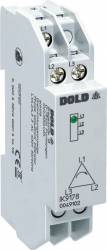
Dold 0049102 IK91783AC50/60HZ400V direction indicator
| Lieske Part No. | 138047 |
|---|---|
| Mfg Part No | 0049102 |
| EAN-Code | 4030641491024 |
| Manufacturer | Dold |
| Here only | 62,03 EUR
73,82 EUR incl. VAT
|
Further information for Dold 0049102 IK91783AC50/60HZ400V direction indicator
| Technical data | |
| 1- / 3-phase | 3 |
| Enclosure design | Distribution board |
| Measuring range max. | 3 AC 400 V |
| Standard measuring range | 3 AC 400 V |
| Width | 17,5 mm |
| Type | IK 9178 |
| Variant | |
| Nominal voltage | 3AC 400 V |
Applications
The IK9178 is used in industrial and installation distributors where correct phase sequence is critical for the safe operation of motors, transformers, or other three-phase consumers. Incorrect phase sequence can cause damage to drives or machinery, which is why continuous monitoring using such a device is common in electrical installations and industrial automation. The device is intended for use in installation and industrial distributors according to DIN 43 880.
Functions and Equipment in Detail
The device features an LED indicator that visually displays the rotation direction. The LED lights up when the phase sequence L1-L2-L3 (clockwise field) is present. If the phase sequence is incorrect, the LED remains off. The indication is provided without auxiliary voltage, meaning the device is directly connected to the three-phase network and requires no additional power supply. The connection terminals are located at the bottom, facilitating installation in standard installation distributors.
Technology Explained Simply
The phase sequence indicator works by measuring the phase shift between the three conductors L1, L2, and L3. The device detects whether the voltages are present in the correct order (L1-L2-L3). The LED lights up only when this sequence is correct. The measurement is performed directly on the network without additional power supply. The rated impulse voltage is 4 kV, ensuring high electrical strength. The housing design is intended for installation distributors, with a width of 17.5 mm and a depth of 59 mm. The housing is made of thermoplastic with V0 behavior according to UL Subject 94, indicating a high flame retardant class.
Compatibility and Accessories
The device is designed for use in three-phase networks with 3 AC 400 V. It is compatible with a DIN rail (top hat rail), enabling installation in standard switchboards. The connection terminals are rated for conductor cross-sections of 0.6 to 2.5 mm² (solid) or 0.28 to 1.5 mm² (stranded wire with ferrule). The stripping length is 10 mm. The terminals are secured using flat terminals with self-lifting connection washers, with a tightening torque of 0.8 Nm.
Mounting and Installation
Mounting is performed on a DIN rail (IEC/EN 60715). The connection terminals are located at the bottom, facilitating wiring in installation distributors according to DIN 43 880. The device dimensions are 17.5 mm (width) × 90 mm (height) × 59 mm (depth). The operating temperature range is between -20 °C and +60 °C, and the storage temperature range is also between -20 °C and +60 °C. The operating altitude is limited to below 2000 m. The housing protection rating is IP 40, and the terminals have a protection rating of IP 20.
Advantages in Operation
The device provides reliable, maintenance-free monitoring of phase sequence without requiring additional power supply. The LED indicator enables quick visual inspection. The mounting width of 17.5 mm makes it compact and suitable for densely packed distributors. Compliance with the standard IEC/EN 60255-1 ensures electrical safety and reliability. The vibration resistance (amplitude 0.35 mm, frequency 10–55 Hz) and climatic resistance (20/060/04) make the device suitable for industrial applications. EMC tests according to IEC/EN 61000-4-2 to -4-6 and radio interference suppression according to EN 55011 Class B ensure electromagnetic compatibility and immunity to interference.

This is an offer of:
79279 Vörstetten
https://industry-electronics.com
Tel. 07666/88499-0
Fax. 07666/88499-111
Diesen Artikel finden Sie unter:
industry-electronics.com/artikel/138047

Lieske Elektronik e.K.
Reutener Str. 1079279 Vörstetten
https://industry-electronics.com
Tel. 07666/88499-0
Fax. 07666/88499-111
Diesen Artikel finden Sie unter:
industry-electronics.com/artikel/138047