
Dold 0049069 standstill monitor 230 V
Industrial Material > Industrial relays and contactors > Switching units / measuring, control relay
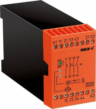
Dold 0049069 standstill monitor 230 V
| Lieske Part No. | 1312732 |
|---|---|
| Mfg Part No | 0049069 |
| EAN-Code | 4030641490690 |
| Manufacturer | Dold |
| Here only | 392,74 EUR
467,36 EUR incl. VAT
|
Further information for Dold 0049069 standstill monitor 230 V
| Technical data | |
| Classification | Stillstandsüberwachung |
| Enclosure design | Switch cabinet |
| Output contacts | 2 NC contacts, 2 NO contacts |
| Width | 45 mm |
| Type | BD 5936 |
| Variant | |
| Auxiliary voltage | AC 230 V 50/60 Hz |
| Contact equipping | 2 NO contacts, 2 NC contacts |
| Approvals and Markings | CCC |
| Variant | With automatic reset for broken wire detection |
Applications
The standstill monitor is designed for industrial applications, particularly for safeguarding machine tools. It can be used, for example, to release safety door interlocks or to activate holding brakes as soon as the motor stops. The function is especially useful in systems where safe shutdown or mechanical interlocking after standstill is required to prevent accidents or damage.
Functions and Equipment in Detail
The device features forced-guided output contacts with 2 normally open and 2 normally closed contacts, rated for AC 250 V. The contacts are mechanically linked to ensure a safe and reliable switching function. LED indicators signal the operating status: a green LED lights up when operating voltage is applied, a second green LED when the motor is at standstill, and a red LED when a wire break is detected in the measurement circuit. The connections for the motor leads (Z1/Z2) can be fitted with wires of 2 x 1.5 mm² (with ferrule and plastic sleeve) or 2 x 2.5 mm² (with ferrule according to DIN 46 228-1/-2/-3/-4).
Technology Explained Simply
The operation is based on measuring the induced voltage in the motor stator during coast-down. When the motor stops, this voltage drops to nearly 0 V, which the device interprets as standstill. The pickup voltage is approximately 20 mV, and the drop-out value is approximately 40 mV. The auxiliary voltage is AC 230 V at a frequency of 50/60 Hz. The nominal power consumption is approximately 3 VA or 3 W. The measurement voltage can reach up to AC 690 V. The electrical life expectancy is approximately 100,000 switching operations at 2 A and AC 230 V, while the mechanical life expectancy is 10 million switching operations.
Compatibility and Accessories
The device is designed for use in enclosures and complies with standards IEC/EN 60255-1 and IEC/EN 60255-26. The width is 45 mm, making it suitable for standard control panels. CCC certification is available. For wiring, it is recommended to route the Z1/Z2 lead separately from the motor supply lead and connect it directly to the motor. For longer cable runs, twisted cables are recommended to minimize interference.
Mounting and Installation
Mounting is done in an enclosure. The terminals are clearly labeled: A1/A2 for auxiliary voltage, Z1/Z2 for motor connection leads, and contacts 11/12/21/22 (normally closed) and 33/34/43/44 (normally open). The terminals are designed for the specified wire cross-sections. Installation requires no additional components, as the device operates independently and does not require external sensors.
Advantages in Operation
The sensorless standstill monitoring reduces the number of required components and lowers maintenance requirements. The integrated wire break detection increases safety, as a defective measurement circuit is immediately recognized. The LED indicators allow for quick visual diagnosis of the operating status. The forced-guided contacts ensure reliable switching, even under difficult operating conditions. The width of 45 mm and the enclosure form factor make the device suitable for standard installations.

This is an offer of:
79279 Vörstetten
https://industry-electronics.com
Tel. 07666/88499-0
Fax. 07666/88499-111
Diesen Artikel finden Sie unter:
industry-electronics.com/artikel/1312732

Lieske Elektronik e.K.
Reutener Str. 1079279 Vörstetten
https://industry-electronics.com
Tel. 07666/88499-0
Fax. 07666/88499-111
Diesen Artikel finden Sie unter:
industry-electronics.com/artikel/1312732