
Dold 0047707 IL9077.12/003 3AC400V 0,1-20S under-voltage over-voltage relay
Industrial Material > Industrial relays and contactors > Switching units / measuring, control relay
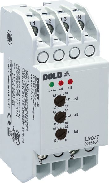
Dold 0047707 IL9077.12/003 3AC400V 0,1-20S under-voltage over-voltage relay
| Lieske Part No. | 970102 |
|---|---|
| Mfg Part No | 0047707 |
| EAN-Code | 4030641477073 |
| Manufacturer | Dold |
| Here only | 276,25 EUR
328,74 EUR incl. VAT
|
Further information for Dold 0047707 IL9077.12/003 3AC400V 0,1-20S under-voltage over-voltage relay
| Technical data | |
| 1- / 3-phase | 1, 3 |
| Auxiliary voltage | Without |
| Enclosure design | Distribution board |
| Measuring range max. | 500 V |
| Output contacts | 2 C/O contacts |
| Standard measuring range | 3/N AC 400/230 V |
| Width | 35 mm |
| Type | IL 9077 |
| Operate delay | |
| Variant | |
| Contact equipping | 2 changeover contacts |
| Nominal voltage | 3AC 400 V |
| Time delay | 0,1 - 20 s |
| Approvals and Markings | CCC |
| Variant | Without neutral connection. De-energized on trip. With phase sequence detection |
Applications
The device is intended for network monitoring in industrial and commercial installations, particularly in systems with self-generated power, such as photovoltaic systems or emergency power units. It enables early detection of voltage fluctuations, phase failures, or incorrect phase sequence to prevent damage to connected equipment. The device is installed in installation distributor enclosures in accordance with DIN 43880, with the I form factor featuring bottom-mounted connection terminals and a mounting depth of 59 mm. The mounting width is 35 mm, enabling compact installation in standard distributors.
Functions and Equipment in Detail
The IL9077.12/003 detects overvoltage (from 0.9 to 1.3 times rated voltage) and undervoltage (from 0.7 to 1.1 times rated voltage) independently. The time delay is adjustable between 0.1 and 20 seconds to filter out short-term voltage fluctuations and avoid false tripping. In the event of a fault, the output relay de-energizes and the green LED turns off. Two red LEDs indicate the type of fault: “<U” for undervoltage and “>U” for overvoltage. Diagnosis is thus performed visually via multiple LEDs.
Technology Explained Simply
The device measures all three phase voltages against the neutral conductor (N). For devices without an N connection, L1 and L2 are measured against L3. In the normal state, a green LED lights up and the output relay is energized. If the set voltage thresholds are exceeded or the minimum voltage is undershot, the relay de-energizes after the set delay time. The return to the normal state occurs only when all phases are within the tolerated voltage ranges. A hysteresis of approximately 4% of the set value prevents chattering. Phase sequence detection is integrated; an incorrect phase sequence is treated as an undervoltage condition, causing the relay to de-energize and the red “<U” LED to light up.
Compatibility and Accessories
The device is designed for single- and three-phase networks and can operate without auxiliary voltage. It complies with the standard IEC/EN 60255-1 and is certified with CCC approval. The IL9077.12/003 variant is available without a neutral conductor connection and includes phase sequence detection. The mounting width of 35 mm allows installation in standard installation distributor enclosures.
Mounting and Installation
Mounting is carried out in installation distributor enclosures in accordance with DIN 43880. The I form factor with bottom-mounted connection terminals and a mounting depth of 59 mm is intended for this application.
Advantages in Operation
The separate adjustability of the trigger values for overvoltage and undervoltage, as well as the adjustable time delay, allows the device to be adapted to different network conditions. The visual fault indication via LEDs enables quick diagnosis. The rest current principle ensures that no additional power supply is required in the event of a fault. Compatibility with single- and three-phase networks increases the flexibility of use. Compliance with the standard IEC/EN 60255-1 ensures reliability and safety of the device in industrial applications.

This is an offer of:
79279 Vörstetten
https://industry-electronics.com
Tel. 07666/88499-0
Fax. 07666/88499-111
Diesen Artikel finden Sie unter:
industry-electronics.com/artikel/970102

Lieske Elektronik e.K.
Reutener Str. 1079279 Vörstetten
https://industry-electronics.com
Tel. 07666/88499-0
Fax. 07666/88499-111
Diesen Artikel finden Sie unter:
industry-electronics.com/artikel/970102