
Dold 0045589 BA9040.12/011 3AC50/60Hz 500V 0.5-5S asymmetrical relay
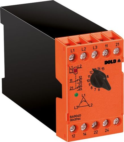
Dold 0045589 BA9040.12/011 3AC50/60Hz 500V 0.5-5S asymmetrical relay
| Lieske Part No. | 1000479 |
|---|---|
| Mfg Part No | 0045589 |
| EAN-Code | 4030641455897 |
| Manufacturer | Dold |
| Here only | 320,41 EUR
381,29 EUR incl. VAT
|
Further information for Dold 0045589 BA9040.12/011 3AC50/60Hz 500V 0.5-5S asymmetrical relay
| Technical data | |
| 1- / 3-phase | 3 |
| Enclosure design | Switch cabinet |
| Measuring range max. | 3 AC 690 V |
| Output contacts | 2 C/O contacts |
| Standard measuring range | 3 AC 400 V |
| Width | 45 mm |
| Type | BA 9040 |
| Operate delay | |
| Variant | |
| Contact equipping | 2 changeover contacts |
| Nominal voltage | 3AC 500 V 50/60 Hz |
| Time delay | 0,5 - 5 s |
| Approvals and Markings | UKCA |
| Variant | With phase sequence detection. With adjustable time delay |
Applications
This relay is intended for use in industrial and commercial installations, particularly in drive technology, where a stable and symmetrical three-phase power supply is required. It protects motors and electrical equipment from damage caused by uneven voltage distribution, phase loss, or incorrect rotation direction. Typical applications include machine controls, conveyor systems, and other systems that rely on continuous and secure power supply.
Functions and Features in Detail
The device detects voltage asymmetry when the voltage difference between phases exceeds a preset threshold. It also monitors phase failure, i.e., the absence of one or more phases in the network. Reverse voltages, i.e., voltages in the opposite direction, are also detected. An integrated phase sequence detection ensures that the phase sequence L1-L2-L3 is correct, which is crucial for the proper rotation direction of motors. The response delay is adjustable between 0.5 and 5 seconds to avoid false tripping during short-term voltage fluctuations.
Technology Explained Simply
The relay operates at a rated voltage of 3AC 500 V at 50/60 Hz. The measurement range extends up to 3 AC 690 V, with the standard measurement range at 3 AC 400 V. The input side receives voltage from the three phases L1, L2, and L3 and continuously compares the values. Upon detection of a fault, the relay switches the output contacts. The output contacts consist of two changeover contacts, used for controlling auxiliary contacts or signal indication. The operating voltage is supplied via terminals L1, L2, L3, with a voltage range coverage of 0.8 to 1.1 times the rated voltage.
Compatibility and Accessories
The device is designed for use in three-phase networks and is compatible with standard network voltages up to 690 V. The connection terminals allow for connection of solid conductors with 2.5 mm² or stranded conductors with 1.5 mm², with terminals conforming to DIN 46228-1/-2/-3/-4. Mounting is done on a DIN rail according to IEC/EN 60715. The width is 45 mm, enabling compact installation in standard enclosures. Indication is provided by two LEDs: a red LED indicates the applied operating voltage, and a green LED signals the activated state of the output relay.
Mounting and Installation
Mounting is done on a DIN rail inside the enclosure. The connection terminals are designed for easy wiring, with conductors to be secured with a tightening torque of 0.8 Nm. The stripping length for conductors is 10 mm. The device dimensions are 45 mm (width) × 74 mm (height) × 133 mm (depth). Installation requires no special tools, as the terminals are self-release. The devices are designed for an operating temperature of 60°C to 75°C.
Advantages in Operation
Early detection of faults enables preventive maintenance and prevents costly damage to drives and motors. The adjustable response delay reduces false tripping during short-term voltage fluctuations. Clear LED indication facilitates diagnosis during operation. Simple wiring and compact design support quick installation and maintenance. The device contributes to operational safety and high availability of the system.
Approvals and Markings
The device carries the UKCA approval, confirming compliance with European safety and operational requirements. Manufacturing is carried out in accordance with standards IEC/EN 60255-1 and IEC/EN 60947-5-1, which apply to electrical monitoring devices and switching devices. Switching capacity is 3 A / 230 V AC (AC 15) and 1 A / 24 V DC (DC 13). The thermal current is 5 A.
Functions and Features in Detail
The device features two changeover contacts as output contacts, which can be used for controlling auxiliary relays, signal indication, or switching functions. The response delay is adjustable between 0.5 and 5 seconds to optimize reaction to faults. Indication is provided by two LEDs: a red LED indicates the applied operating voltage, and a green LED signals the activated state of the relay. The conductor terminals are designed for 2.5 mm² solid conductors or 1.5 mm² stranded conductors, with terminals conforming to DIN 46228-1/-2/-3/-4.
Technology Explained Simply
The relay continuously monitors the three phases L1, L2, and L3. Upon detection of asymmetry, phase failure, reverse voltage, or incorrect phase sequence, the output contact is switched. The rated voltage is 3AC 500 V, with a measurement range up to 690 V. The frequency range coverage is between 45 and 65 Hz. The voltage range coverage is 0.8 to 1.1 times the rated voltage. The operating voltage is supplied via terminals L1, L2, L3.
Compatibility and Accessories
The device is designed for use in three-phase networks and is compatible with standard network voltages up to 690 V. The connection terminals allow for connection of solid conductors with 2.5 mm² or stranded conductors with 1.5 mm², with terminals conforming to DIN 46228-1/-2/-3/-4. Mounting is done on a DIN rail according to IEC/EN 60715. The width is 45 mm, enabling compact installation in standard enclosures. Indication is provided by two LEDs: a red LED indicates the applied operating voltage, and a green LED signals the activated state of the output relay.
Mounting and Installation
Mounting is done on a DIN rail inside the enclosure. The connection terminals are designed for easy wiring, with conductors to be secured with a tightening torque of 0.8 Nm. The stripping length for conductors is 10 mm. The device dimensions are 45 mm (width) × 74 mm (height) × 133 mm (depth). Installation requires no special tools, as the terminals are self-release. The devices are designed for an operating temperature of 60°C to 75°C.
Advantages in Operation
Early detection of faults enables preventive maintenance and prevents costly damage to drives and motors. The adjustable response delay reduces false tripping during short-term voltage fluctuations. Clear LED indication facilitates diagnosis during operation. Simple wiring and compact design support quick installation and maintenance. The device contributes to operational safety and high availability of the system.
Approvals and Markings
The device carries the UKCA approval, confirming compliance with European safety and operational requirements. Manufacturing is carried out in accordance with standards IEC/EN 60255-1 and IEC/EN 60947-5-1, which apply to electrical monitoring devices and switching devices. Switching capacity is 3 A / 230 V AC (AC 15) and 1 A / 24 V DC (DC 13). The thermal current is 5 A.

This is an offer of:
79279 Vörstetten
https://industry-electronics.com
Tel. 07666/88499-0
Fax. 07666/88499-111
Diesen Artikel finden Sie unter:
industry-electronics.com/artikel/1000479

Lieske Elektronik e.K.
Reutener Str. 1079279 Vörstetten
https://industry-electronics.com
Tel. 07666/88499-0
Fax. 07666/88499-111
Diesen Artikel finden Sie unter:
industry-electronics.com/artikel/1000479