
Dold 0045381 BD9080.12 3AC690V UH AC230V 0,1-5s phase monitor
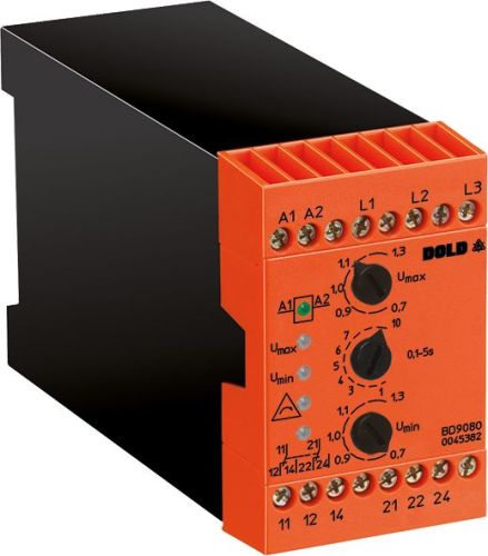
Dold 0045381 BD9080.12 3AC690V UH AC230V 0,1-5s phase monitor
| Lieske Part No. | 1002073 |
|---|---|
| Mfg Part No | 0045381 |
| EAN-Code | 4030641453817 |
| Manufacturer | Dold |
| Here only | 387,92 EUR
461,62 EUR incl. VAT
|
Further information for Dold 0045381 BD9080.12 3AC690V UH AC230V 0,1-5s phase monitor
| Technical data | |
| 1- / 3-phase | 3 |
| Enclosure design | Switch cabinet |
| Measuring range max. | 750 V |
| Output contacts | 2 C/O contacts |
| Standard measuring range | 3 AC 400 V |
| Width | 45 mm |
| Type | BD 9080 |
| Operate delay | |
| Variant | |
| Auxiliary voltage | AC 230 V |
| Contact equipping | 2 changeover contacts |
| Nominal voltage | 3AC 690 V |
| Release delay | 0,1 - 5 s |
| Approvals and Markings | CCC |
| Variant | De-Energized on trip |
Applications
The phase monitor BD9080.12 is suitable for use in industrial plants, such as in manufacturing, power supply, or automation technology. It monitors three-phase networks with a nominal voltage of 3AC 690 V and can also be used at other voltages in the range of 230 V to 750 V, provided they fall within the setting range of 0.7 to 1.3 times the nominal voltage. Monitoring is independent of whether the network has a neutral conductor or not. The devices are designed for continuous operation and can be operated in environments with temperatures from -20 °C to +60 °C.
Functions and Equipment in Detail
The device features two changeover contacts as output contacts, which can be used for signaling faults or controlling auxiliary functions. The response delay of 0.1 to 5 seconds allows for differentiated reaction to short-term voltage fluctuations, avoiding false alarms. The reset delay is also adjustable in the same range to ensure stable reset after fault correction. The LED indicators signal the operating status: one LED for auxiliary voltage A1/A2, one for overvoltage (U max.), one for undervoltage (U min.), one for asymmetry, incorrect phase sequence, or network failure, and one LED for the contact position of the output relay.
Technology Explained Simply
Measurement is performed by arithmetic averaging of multiple half-waves of the rectified phase voltages L1/L2 and L2/L3, with L3 serving as the reference voltage. Asymmetry detection occurs at a deviation of ±8 to ±20 % of the response voltage, with the fault angle being approximately 120° ±15°. The repeatability is ≤ ±0.5 % of the nominal voltage, and the hysteresis is ≤5 % of the response value. The current consumption per phase is approximately 0.5 mA (L1, L2) and 0.8 mA (L3) at nominal voltage. The auxiliary voltage can also be drawn from the monitored network, thereby reducing the permissible voltage range of the network to 0.8 to 1.1 times the auxiliary voltage.
Compatibility and Accessories
The phase monitor BD9080.12 is designed for mounting in enclosures and has a width of 45 mm. It is specified according to IEC/EN 60255-1 and carries the CCC certification. The output contacts are rated for circuits according to AC 15 (2 A / AC 230 V) and DC 13 (1 A / DC 24 V). The electrical life is approximately 250,000 switching operations at 1 A and AC 230 V, and the mechanical life is at least 50 million switching operations. The maximum short-circuit withstand requires a fuse with 4 A gG/gL. The device is suitable for operation at altitudes up to 2000 m above sea level.
Mounting and Installation
Mounting is done in an enclosure, taking into account the width of 45 mm. Connections are made via terminals: L1, L2, L3 for phase voltage, A1/A2 for auxiliary voltage, and contacts 11-12-14 and 21-22-24 for the output relays. The devices are designed for continuous operation and require no special mounting aids. The LED indicators enable quick visual fault diagnosis.
Advantages in Operation
By detecting voltage fluctuations, asymmetry, or phase failure early, the device can protect connected machines and systems from damage. The adjustable response delay reduces false alarms during short-term disturbances. The LED indicators enable quick fault localization. The high life expectancy and reliability of the contacts ensure long-term operation without maintenance. Compatibility with various voltage levels and the ability to draw auxiliary voltage from the monitored network increase installation flexibility.
Certifications and Markings
The device carries the CCC certification and complies with the standard IEC/EN 60255-1. The creepage and clearance distances correspond to the rated impulse voltage of 6 kV and pollution degree 2, according to IEC 60664-1. The operating temperature is between -20 °C and +60 °C, and the storage temperature is also between -20 °C and +60 °C.
Functions and Display
The LED indicators signal: auxiliary voltage (A1/A2), overvoltage (U max.), undervoltage (U min.), asymmetry / incorrect phase sequence / network failure, and the contact position of the output relay. The display enables quick visual diagnosis of the operating status. The response delay of 0.1 to 5 seconds prevents false alarms during short-term disturbances. The reset delay is also adjustable in the range of 0.1 to 5 seconds to ensure stable reset after fault correction.

This is an offer of:
79279 Vörstetten
https://industry-electronics.com
Tel. 07666/88499-0
Fax. 07666/88499-111
Diesen Artikel finden Sie unter:
industry-electronics.com/artikel/1002073

Lieske Elektronik e.K.
Reutener Str. 1079279 Vörstetten
https://industry-electronics.com
Tel. 07666/88499-0
Fax. 07666/88499-111
Diesen Artikel finden Sie unter:
industry-electronics.com/artikel/1002073