
Dold 0041732 BA90413AC50HZ400V phase sequence relay
Industrial Material > Industrial relays and contactors > Switching units / measuring, control relay
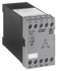
Dold 0041732 BA90413AC50HZ400V phase sequence relay
| Lieske Part No. | 140934 |
|---|---|
| Mfg Part No | 0041732 |
| EAN-Code | 4030641417321 |
| Manufacturer | Dold |
| Here only | 201,52 EUR
239,81 EUR incl. VAT
|
Further information for Dold 0041732 BA90413AC50HZ400V phase sequence relay
| Technical data | |
| 1- / 3-phase | 3 |
| Enclosure design | Switch cabinet |
| Measuring range max. | 500 V |
| Output contacts | 2 C/O contacts |
| Standard measuring range | 3 AC 400 V |
| Width | 45 mm |
| Type | BA 9041 |
| Variant | |
| Contact equipping | 2 changeover contacts |
| Nominal voltage | 3AC 400 V 50 Hz |
Applications
This relay is used in industrial and commercial installations where correct phase sequence is critical for the safe operation of three-phase motors. It is suitable for networks with a nominal voltage of 3AC 400 V at 50 Hz, with a voltage range between 0.8 and 1.1 times the nominal voltage. The maximum measuring voltage is 500 V, allowing use in networks with slightly increased voltage. The operating temperature ranges from -20 °C to +60 °C, enabling use in indoor installations and under industrial conditions.
Functions and Equipment in Detail
The device features two changeover contacts as output contacts, which switch to the operating position when the correct phase sequence and presence of all three phase voltages are detected. Contacts 11-14 and 21-24 close, and a green LED lights up, visually indicating the operating status. In case of a phase failure or incorrect phase sequence, the relay is de-energized, causing the output contacts to return to their default position. The response time is less than 100 ms, and the reset time is less than 50 ms, enabling rapid reaction to disturbances.
Technology Explained Simply
The phase sequence relay detects whether phases L1, L2, and L3 are present in the correct order. If any phase drops below 60 % of nominal voltage, the device is de-energized. For recovery voltages above 60 % of nominal voltage, no fault message is triggered, as these may be caused by connected loads. In networks with thyristor controls or high harmonic content, the device may produce false results, as commutation spikes or harmonics may mimic a phase failure. In such cases, it is recommended to test a sample device on-site to verify suitability.
Compatibility and Accessories
The device is designed for use in 3-phase AC networks. It can be combined with other monitoring devices, such as the asymmetry relay BA 9040, to detect additional disturbances like voltage asymmetries. The connection terminals are designed for 2 x 2.5 mm² single or 2 x 1.5 mm² stranded cable with shrink or screw ferrules according to DIN 46228. Mounting is done on a DIN rail according to IEC/EN 60715.
Mounting and Installation
Mounting is performed on a standard DIN rail inside the enclosure. Cable connections are made via flat terminals with self-lifting spring clamps according to IEC/EN 60999-1. The required tightening torque is 0.8 Nm. The width is 45 mm, and overall dimensions are 45 mm (width) × 73.2 mm (height) × 119.8 mm (depth). The enclosure protection rating is IP 40, protecting against contact with moving parts and solid objects, but not against water or dust.
Operational Advantages
Monitoring of phase sequence ensures correct rotation direction of drives, preventing damage to machines and systems. Simple wiring and clear visual indication via the green LED simplify commissioning and maintenance. The mechanical life is at least 50 million switching operations, and the electrical life at 3 A and AC 230 V is 250,000 switching operations. Short-circuit resistance is ensured with a maximum fuse rating of 4 A gG/gL according to IEC/EN 60947-5-1. The device is designed for continuous operation and is suitable for industrial applications with high reliability requirements.
Protection Rating and Environmental Conditions
The enclosure is made of thermoplastic material with V0 flammability rating according to UL 94, indicating a high fire protection class. The IP 40 protection rating protects against contact with moving parts and solid objects, but not against water. The operating altitude is limited to a maximum of 2000 m above sea level. EMC requirements are met according to IEC/EN 61000-4-2 to -4-6, including immunity to electrostatic discharge (8 kV), high-frequency radiation (10 V/m), and fast transients (2 kV). Radio frequency interference suppression complies with Class B limits according to EN 55011.
Contact Configuration and Switching Capacity
The contact configuration includes two changeover contacts rated for a switching current of 2 A at AC 230 V (make) and 1 A at AC 230 V (break) according to IEC/EN 60947-5-1. The thermal current is 5 A. The nominal power consumption is less than 3.5 VA. The terminals are designed for connection with solid or stranded cables, with a stripping length of 10 mm.
Approvals and Markings
The device complies with standards IEC/EN 60255-1, IEC/EN 60947-5-1, IEC/EN 60529 (protection rating IP 40), IEC/EN 61000-4-2 to -4-6 (EMC), and EN 55011 (radio frequency interference). The overvoltage category is III for 3 AC 480 V and II for 3 AC 500 V. The rated impulse withstand voltage is 4 kV at pollution degree 2 according to IEC 60664-1.

This is an offer of:
79279 Vörstetten
https://industry-electronics.com
Tel. 07666/88499-0
Fax. 07666/88499-111
Diesen Artikel finden Sie unter:
industry-electronics.com/artikel/140934

Lieske Elektronik e.K.
Reutener Str. 1079279 Vörstetten
https://industry-electronics.com
Tel. 07666/88499-0
Fax. 07666/88499-111
Diesen Artikel finden Sie unter:
industry-electronics.com/artikel/140934