
Dold 0032847 IK3076.12 AC50/60Hz 230-240V coupling relay
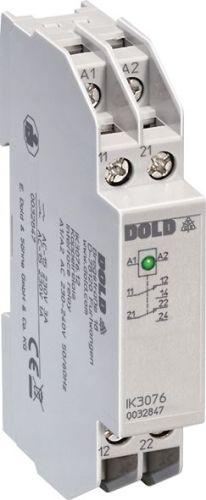
Dold 0032847 IK3076.12 AC50/60Hz 230-240V coupling relay
| Lieske Part No. | 1001817 |
|---|---|
| Mfg Part No | 0032847 |
| EAN-Code | 4030641328474 |
| Manufacturer | Dold |
| Here only | 71,16 EUR
84,68 EUR incl. VAT
|
Further information for Dold 0032847 IK3076.12 AC50/60Hz 230-240V coupling relay
| Technical data | |
| Enclosure design | Distribution board |
| Output contacts max. | 2 C/O contacts |
| Thermal current Ith max. | 10 A |
| Width | 17,5 mm |
| Type | IK 3076 |
| Initiator triggering | |
| Suppressor circuit on the coil input | |
| Variant | |
| Contact equipping | 2 changeover contacts |
| Nominal voltage | AC 230 - 240 V |
Applications
The IK3076.12 coupling relay is used in systems where galvanic isolation between control and power circuits is required. It enables the control of multiple loads from a single control signal, which is advantageous in complex control systems. Application areas include industrial manufacturing, building automation, and signal and switching technology in rail vehicle technology.
Functions and Equipment in Detail
The device is equipped with two changeover contacts designed for switching loads in the AC 15 and DC 13 categories. The contact configuration allows control of loads with a thermal current Ith of up to 5 A. The pickup and drop-out time is less than 10 ms and less than 20 ms respectively, ensuring a fast response to control signals. An integrated green LED indicator signals the energized state of the relay. The input protection circuit protects the device against voltage surges and increases operational safety.
Technology Explained Simply
The rated voltage is AC 230–240 V at a frequency of 50/60 Hz. The relay operates in continuous duty and is designed for operating temperatures from -25 °C to +60 °C. The switching capacity according to AC 15 is 3 A at 230 V for the make contact and 1 A for the break contact. For DC 13, the switching capacity is 1 A at 24 V for both make and break contacts. The electrical life is 1 x 10⁵ switching operations at 3 A and 230 V AC. The mechanical life exceeds 30 x 10⁶ switching operations. The permissible switching frequency is 6000 switching operations per hour. The short-circuit withstand capability is defined with a maximum fuse rating of 4 A gG/gL according to IEC/EN 60947-5-1.
Compatibility and Accessories
The coupling relay is equipped with an input protection circuit that limits voltage surges at the coil input. It is designed for single-phase systems (same phase). The connection terminals are rated for conductor cross-sections of 2 x 2.5 mm² (solid) or 2 x 1.5 mm² (stranded wire with sleeve according to DIN 46228-1/-2/-3/-4). The stripping length is 10 mm. The terminal fastening is done via flat terminals with self-lifting connection washers according to IEC/EN 60999-1. The housing is made of thermoplastic with V0 flammability rating according to UL Subj. 94.
Mounting and Installation
Mounting is either on a DIN rail (IEC/EN 60715) or via screw mounting with M4 screws on a 90 mm grid. The terminals are located at the bottom, which facilitates integration into installation and industrial distributors according to DIN 43880. The depth of 59 mm and width of 17.5 mm allow for compact placement in enclosures.
Operational Advantages
The IK3076.12 coupling relay complies with standards IEC/EN 60947-5-1 and IEC/EN 61810-1. It provides safe isolation according to IEC/EN 61140 and IEC/EN 60947-1 when equipped with a changeover contact. The integrated LED indicator enables visual monitoring of the operating state. The input protection circuit increases the reliability and protective function of the device. The high mechanical life and short response time make it suitable for demanding industrial applications. The housing protection rating is IP 40, and the terminals are rated IP 20. The operating altitude is limited to a maximum of 2000 m. The vibration resistance is specified as an amplitude of 0.35 mm at a frequency of 10 to 55 Hz according to IEC/EN 60068-2-6. The climatic resistance is specified according to IEC/EN 60068-1 with 25/060/04. The conductor connection terminals comply with standard EN 50005.
Protection Rating and EMC
The housing has a protection rating of IP 40 according to IEC/EN 60529, protecting against contact with solid objects and splashing water. The terminals have a protection rating of IP 20. The rated impulse voltage is 4 kV for input and output, and 2.5 kV for contacts at pollution degree 2 according to IEC 60664-1. EMC requirements include immunity to electrostatic discharge (8 kV air discharge), RF radiation (10 V/m up to 1 GHz, 3 V/m up to 2.5 GHz, 1 V/m up to 2.7 GHz), fast transients (2 kV), and surge voltages (1 kV between supply lines, 2 kV between line and earth). Radio frequency interference suppression complies with emission limit class B according to EN 55011.
Permissible Operating Conditions
The device is designed for operation at ambient temperatures from -25 °C to +60 °C. The storage temperature may range from -40 °C to +80 °C. The operating altitude is limited to a maximum of 2000 m above sea level. The operating mode is continuous duty. The rated frequency is 50/60 Hz with a frequency range of ±5 %. The voltage range coverage is 0.8 to 1.1 times the rated voltage, and for battery operation, 0.9 to 1.25 times the rated voltage.
Connection Terminals and Conductor Fastening
The connection terminals are rated for conductor cross-sections of 2 x 2.5 mm² (solid) or 2 x 1.5 mm² (stranded wire with sleeve according to DIN 46228-1/-2/-3/-4). The stripping length is 10 mm. Fastening is done via flat terminals with self-lifting connection washers according to IEC/EN 60999-1. The tightening torque is 0.8 Nm. Terminal marking follows EN 50005.
Contact Configuration
The contact configuration includes two changeover contacts designed for switching loads in the AC 15 and DC 13 categories. The switching capacity is 3 A/230 V AC for the make contact and 1 A/230 V AC for the break contact. For DC 13, the switching capacity is 1 A/24 V for both make and break contacts. The electrical life is 1 x 10⁵ switching operations at 3 A and 230 V AC. The mechanical life exceeds 30 x 10⁶ switching operations. The permissible switching frequency is 6000 switching operations per hour. The short-circuit withstand capability is defined with a maximum fuse rating of 4 A gG/gL according to IEC/EN 60947-5-1.
Thermal Current and Switching Capacity
The thermal current Ith is up to 5 A. The switching capacity according to AC 15 is 3 A at 230 V for the make contact and 1 A for the break contact. For DC 13, the switching capacity is 1 A at 24 V for both make and break contacts. The electrical life is 1 x 10⁵ switching operations at 3 A and 230 V AC. The mechanical life exceeds 30 x 10⁶ switching operations. The permissible switching frequency is 6000 switching operations per hour. The short-circuit withstand capability is defined with a maximum fuse rating of 4 A gG/gL according to IEC/EN 60947-5-1.
Protection Rating and EMC
The housing has a protection rating of IP 40 according to IEC/EN 60529, protecting against contact with solid objects and splashing water. The terminals have a protection rating of IP 20. The rated impulse voltage is 4 kV for input and output, and 2.5 kV for contacts at pollution degree 2 according to IEC 60664-1. EMC requirements include immunity to electrostatic discharge (8 kV air discharge), RF radiation (10 V/m up to 1 GHz, 3 V/m up to 2.5 GHz, 1 V/m up to 2.7 GHz), fast transients (2 kV), and surge voltages (1 kV between supply lines, 2 kV between line and earth). Radio frequency interference suppression complies with emission limit class B according to EN 55011.
Permissible Operating Conditions
The device is designed for operation at ambient temperatures from -25 °C to +60 °C. The storage temperature may range from -40 °C to +80 °C. The operating altitude is limited to a maximum of 2000 m above sea level. The operating mode is continuous duty. The rated frequency is 50/60 Hz with a frequency range of ±5 %. The voltage range coverage is 0.8 to 1.1 times the rated voltage, and for battery operation, 0.9 to 1.25 times the rated voltage.
Connection Terminals and Conductor Fastening
The connection terminals are rated for conductor cross-sections of 2 x 2.5 mm² (solid) or 2 x 1.5 mm² (stranded wire with sleeve according to DIN 46228-1/-2/-3/-4). The stripping length is 10 mm. Fastening is done via flat terminals with self-lifting connection washers according to IEC/EN 60999-1. The tightening torque is 0.8 Nm. Terminal marking follows EN 50005.

This is an offer of:
79279 Vörstetten
https://industry-electronics.com
Tel. 07666/88499-0
Fax. 07666/88499-111
Diesen Artikel finden Sie unter:
industry-electronics.com/artikel/1001817

Lieske Elektronik e.K.
Reutener Str. 1079279 Vörstetten
https://industry-electronics.com
Tel. 07666/88499-0
Fax. 07666/88499-111
Diesen Artikel finden Sie unter:
industry-electronics.com/artikel/1001817