
Dold 0031734 time relay MK9961.35 230V 30-600s delayed-off
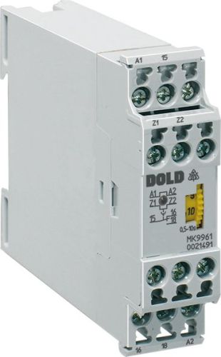
Dold 0031734 time relay MK9961.35 230V 30-600s delayed-off
| Lieske Part No. | 1153978 |
|---|---|
| Mfg Part No | 0031734 |
| EAN-Code | 4030641317348 |
| Manufacturer | Dold |
| Here only | 320,99 EUR
381,98 EUR incl. VAT
|
Further information for Dold 0031734 time relay MK9961.35 230V 30-600s delayed-off
| Technical data | |
| Approvals | UL |
| Enclosure design | Switch cabinet |
| Output contacts | 1 C/O contact |
| Time function(s) | Off-delay, without control signal |
| Width | 22,5 mm |
| Type | MK 9961 |
| Variant | |
| Contact equipping | 1 NO contact undelayed, 1 changeover contact delayed |
| Nominal voltage | AC 230 V |
| Time range | 30 - 600 s |
| Variant | Release delay, without control signal |
Applications
This time relay is designed for applications requiring delayed deactivation after interruption of the operating voltage. Typical use cases include controlling pumps, fans, or lighting systems, where controlled function decay is necessary to avoid mechanical or electrical stress. The zero-voltage safety ensures the relay maintains its function even during brief power outages.
Functions and Equipment in Detail
The device features contact configuration with one instantaneous closer and one delayed changeover contact. The changeover contact switches with delay when the operating voltage is switched off, thereby achieving the drop-out delay. The time delay is continuously adjustable and set on an absolute scale. Remote adjustment is possible via an external variable resistor, allowing the time delay to be adjusted from outside the enclosure. An LED indicator signals the presence of operating voltage.
Technology Explained Simply
The time function is based on an electronic timer that keeps the output contacts active for the set duration after switching off the operating voltage. The delay is controlled by an internal capacitor and resistor, with the duration adjustable via an external variable resistor. The contact materials consist of AgSnO₂ for the changeover contact and AgNi for the closer, ensuring high switching durability and corrosion resistance. The thermal current rating is 2 A, and the switching capacity is 3 A/AC 230 V for the closer.
Compatibility and Accessories
The relay is designed for mounting on a DIN rail and can be combined with external variable resistors to adjust the time delay. The part numbers for compatible external variable resistors are listed in the datasheet, for example, a 4.7 MΩ resistor is used for the 30 s time range. The operating voltage range is AC 110 to 127 V and AC 230 V, with the rated voltage being AC 230 V. The frequency range covers ±5 % of the nominal frequency of 50/60 Hz.
Mounting and Installation
Mounting is on a DIN rail inside the enclosure. The terminal clamps are designed for cable cross-sections up to 2 x 1.5 mm², with cables to be fitted with heat shrink tubing or protective sleeves according to DIN 46228-1/-2/-3/-4. Fixing is done via flat clamps with self-lifting clamp jaws. The device is designed for operating temperatures from -20 to +60 °C and can be used up to an altitude of 2000 m above sea level.
Operational Advantages
The time relay offers high operational safety through zero-voltage safety and precise time control with low repeatability deviation. Remote adjustment enables flexible adaptation of the delay time without physical access to the device. The LED indicator facilitates diagnosis and monitoring of the operating status. The mechanical life is 50 million switching operations, enabling long-term use without maintenance. The electrical life is 3 x 10⁵ switching operations at 3 A/AC 230 V.
Approvals and Environmental Conditions
The device is UL-approved and meets the requirements of IEC/EN 60947-5-1 for switching devices. The enclosure protection rating is IP 40, and the terminal clamp protection rating is IP 20. The overvoltage category is III, and the rated impulse withstand voltage is 4 kV at pollution degree 2. EMC requirements are met according to IEC/EN 61000-4-2 to -4-6, protecting the device against electromagnetic interference. The operating altitude is limited to 2000 m, and storage is in the temperature range of -20 to +60 °C.
Enclosure and Mounting
The enclosure is made of thermoplastic with V0 flammability rating according to UL 94. Vibration resistance is tested for an amplitude of 0.35 mm and frequencies from 10 to 55 Hz according to IEC/EN 60068-2-6. Climate resistance corresponds to test 20/060/04 according to IEC/EN 60068-1. Mounting is on a DIN rail, with dimensions of 22.5 mm (width) x 82 mm (height) x 99 mm (depth). The device weighs 140 g.
Terminal Designations
The terminal clamps are assigned as follows: A1 (L/+) and A2 (N/-) for operating voltage, 15, 16, 18 for the delayed changeover contact, 23, 24 for the instantaneous closer contact, and Z1, Z2 for connecting an external variable resistor for remote time delay adjustment.
Approvals and Standards
The device complies with standard EN 61812-1 for time relays and is UL-approved. EMC requirements are met according to IEC/EN 61000-4-2 to -4-6. Insulation testing is performed at 2.5 kV for 1 minute. The overvoltage category III and rated impulse withstand voltage of 4 kV at pollution degree 2 are relevant for safe operating environment.
Operating Environment
The device is designed for operating temperatures from -20 to +60 °C and can be used up to an altitude of 2000 m above sea level. Storage is in the same temperature range. The enclosure protection rating IP 40 and terminal clamp protection rating IP 20 protect against contact and dust, but not against water. Climate resistance is tested according to IEC/EN 60068-1, test 20/060/04.
Switching Capacity and Life
The switching capacity according to AC 15 is 3 A/AC 230 V for the closer and 1 A/AC 230 V for the opener. The electrical life is 3 x 10⁵ switching operations at 3 A/AC 230 V, and the mechanical life is 50 x 10⁶ switching operations. The permissible switching frequency is 3000 switching operations per hour.
Connection and Mounting
The terminal clamps are designed for cable cross-sections up to 2 x 1.5 mm², with cables to be fitted with heat shrink tubing or protective sleeves according to DIN 46228-1/-2/-3/-4. Fixing is done via flat clamps with self-lifting clamp jaws. Mounting is on a DIN rail, with dimensions of 22.5 mm (width) x 82 mm (height) x 99 mm (depth). The device weighs 140 g.
There are no conflicting statements regarding technical data, contact configuration, time function, or approvals.

This is an offer of:
79279 Vörstetten
https://industry-electronics.com
Tel. 07666/88499-0
Fax. 07666/88499-111
Diesen Artikel finden Sie unter:
industry-electronics.com/artikel/1153978

Lieske Elektronik e.K.
Reutener Str. 1079279 Vörstetten
https://industry-electronics.com
Tel. 07666/88499-0
Fax. 07666/88499-111
Diesen Artikel finden Sie unter:
industry-electronics.com/artikel/1153978