
Dold 0029294 BA9043/002 3/N AC50-400Hz 240/415V undervoltage relay 0.5-10s
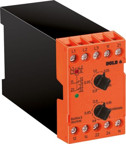
Dold 0029294 BA9043/002 3/N AC50-400Hz 240/415V undervoltage relay 0.5-10s
| Lieske Part No. | 1153822 |
|---|---|
| Mfg Part No | 0029294 |
| EAN-Code | 4030641292942 |
| Manufacturer | Dold |
| Here only | 293,22 EUR
348,93 EUR incl. VAT
|
Further information for Dold 0029294 BA9043/002 3/N AC50-400Hz 240/415V undervoltage relay 0.5-10s
| Technical data | |
| 1- / 3-phase | 3 |
| Auxiliary voltage | Without |
| Enclosure design | Switch cabinet |
| Nominal voltage max. | 3/N AC 690 / 400 V |
| Output contacts | 2 C/O contacts |
| Width | 45 mm |
| Type | BA 9043 |
| Operate delay | |
| Variant | |
| Contact equipping | 2 changeover contacts |
| Nominal voltage | 3/N 240/415 V |
| Time delay | 0,5 - 10 s |
| Approvals and Markings | UKCA |
| Variant | For 3p4w systems. With adjustable time delay |
Applications
This relay is designed for use in industrial and railway applications where reliable voltage monitoring of three-phase networks is required. It is particularly suitable for systems requiring high availability and rapid fault localization. The device is installed in enclosures and has a width of 45 mm, allowing integration into standard DIN rail mounting. The operating temperature range is from -20 °C to +60 °C, and the storage temperature range is from -25 °C to +60 °C. The operating altitude is limited to a maximum of 2000 m above sea level.
Functions and Equipment in Detail
The device features two changeover contacts that function as output relays. These are designed according to the rest current principle, meaning they are not activated in the event of a fault, enabling safe and clear signaling. The contacts are rated for a maximum thermal current of 6 A per contact and meet switching capacities according to AC 15 (make: 2 A / AC 230 V, break: 1 A / AC 230 V) and DC 13 (1 A / DC 24 V). The electrical life expectancy is at least 200,000 switching operations at 3 A and AC 230 V, while the mechanical life expectancy exceeds 30 million switching operations. Short-circuit resistance is ensured with a maximum fuse rating of 4 A gG / gL.
Technology Explained Simply
Voltage monitoring is achieved by measuring each phase against the neutral conductor, followed by arithmetic averaging. This enables precise detection of network voltage, even under unbalanced loads. The immunity to harmonics ensures the device is not falsely triggered by harmonic distortions in the network. LED indicators show operational readiness (red LED) and activation of the output relay (green LED), allowing visual verification of the operating status. The devices are specified according to IEC/EN 60255-1 and meet EMC requirements, including immunity to static discharge (8 kV), high-frequency radiation (20 V/m), fast transients (2 kV), and surge voltages (1 kV between supply lines, 2 kV between lines and earth).
Compatibility and Accessories
The relay is available for networks with or without neutral conductor, with the BA9043/002 variant specifically designed for systems with neutral conductor. It is available for nominal voltages from 3/N AC 100/57 V to 690/400 V, with the specified variant covering 240/415 V. The devices are suitable for frequencies from 50 to 400 Hz and can be used in industrial and railway applications. Mounting is done via DIN rails, and the terminals are designed for 2 x 2.5 mm² solid or 2 x 1.5 mm² stranded conductors. Fixing is done using M3.5 plus-minus screws with self-lifting clamp lever, with a tightening torque of 0.8 Nm.
Mounting and Installation
Installation is performed in enclosures using DIN rail mounting. The connection terminals are designed for connection with solid or stranded conductors, with standardized dimensions and fixing screws. Wiring is done via terminals L1, L2, L3 and N for the network side, and 11, 12, 14 and 21, 22, 24 for the output contacts. Adjustment of pickup and dropout values as well as time delay is done via potentiometers on the front of the device.
Operational Advantages
Preventive maintenance is supported by early detection of voltage drops, increasing productivity and accelerating fault localization. LED indicators allow for quick visual verification of the operating status. Immunity to harmonics ensures stable operation even in electrically demanding environments. The adjustable time delay allows adaptation to the specific requirements of the system, preventing unwanted tripping during short-term voltage dips. The rest current principle design ensures clear signaling of the tripping state, as the contacts are not activated during a fault.
Approvals and Markings
The device carries the UKCA approval, confirming compliance with applicable European safety and operational requirements. The devices comply with IEC/EN 60255-1, the standard for electrical equipment in measurement and monitoring technology. EMC requirements are met according to IEC/EN 61000-4-2 to -4-5, ensuring immunity to electromagnetic influences. The overvoltage category III and rated impulse voltage of 6 kV at pollution degree 2 are suitable for industrial applications. Vibration and shock resistance corresponds to category 1, class B according to IEC/EN 61373, ensuring suitability for use in moving systems such as railway applications.

This is an offer of:
79279 Vörstetten
https://industry-electronics.com
Tel. 07666/88499-0
Fax. 07666/88499-111
Diesen Artikel finden Sie unter:
industry-electronics.com/artikel/1153822

Lieske Elektronik e.K.
Reutener Str. 1079279 Vörstetten
https://industry-electronics.com
Tel. 07666/88499-0
Fax. 07666/88499-111
Diesen Artikel finden Sie unter:
industry-electronics.com/artikel/1153822