
Dold 0029209 ML9701.11 AC/DC0,8-1,6A current relay
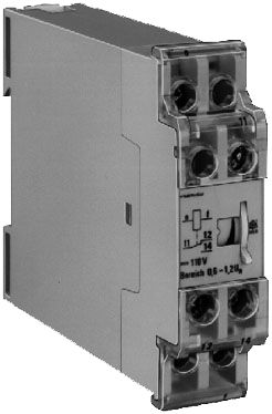
Dold 0029209 ML9701.11 AC/DC0,8-1,6A current relay
| Lieske Part No. | 1153655 |
|---|---|
| Mfg Part No | 0029209 |
| EAN-Code | 4030641292096 |
| Manufacturer | Dold |
| Here only | 236,34 EUR
281,24 EUR incl. VAT
|
Further information for Dold 0029209 ML9701.11 AC/DC0,8-1,6A current relay
| Technical data | |
| 1- / 3-phase | 1 |
| Auxiliary voltage | Without |
| Enclosure design | Switch cabinet |
| Output contacts | 1 C/O contact |
| Width | 22,5 mm |
| Type | ML 9701 |
| Variant | |
| Contact equipping | 1 changeover contact |
| Measuring range | AC/DC 0,8 - 1,6 A |
Applications
This current relay is designed for use in industrial and technical installations where reliable current monitoring is required. It is frequently used in heating systems to detect unexpected current drops or rises, which may indicate a defect or malfunction. In motor monitoring applications, it detects overloads or underloads to prevent damage to motors or connected devices. Its use as an under- or overcurrent relay enables flexible integration into various circuits.
Functions and Equipment in Detail
The device features contact configuration with one changeover contact (1 C/O contact), which can be used to control auxiliary circuits or alarms. The contacts are rated for a switching current of up to 2 A at 230 V AC. The thermal rating is 4 A, enabling use in installations with short-term overloads. The dropout ratios (hysteresis) are approximately 0.85 for AC and 0.5 for DC, ensuring stable switching behavior under slightly fluctuating loads.
Technology Explained Simply
The current relay operates purely electromechanically, meaning it contains no electronic components for signal processing. As a result, it is insensitive to high voltage spikes and disturbances in the radio frequency range. Additional suppression circuits are not required. Measurement is performed via terminals i and k, which are directly connected into the circuit to be monitored. The output contacts (11, 12, 14) switch when the set pickup value is reached. The adjustable range of 1:2 allows flexible adaptation to different loads.
Compatibility and Accessories
The device is designed for installation in enclosures and is mounted on a DIN rail. The width is 22.5 mm, enabling compact placement in standard control panels. The terminals are rated for conductor cross-sections of 2 x 2.5 mm² (solid) or 2 x 1.5 mm² (stranded wire with ferrule). The connection terminals comply with standard EN 50005. The maximum fuse rating is 2 A gG/gL, ensuring safety in case of fault.
Mounting and Installation
Mounting is on a DIN rail within the enclosure. Terminals i and k are intended for direct connection into the current circuit. When mounting multiple relays in close proximity, correct polarity must be observed: for DC operation, all relays must be polarized in the same direction; for single-phase AC, terminals i must be connected in phase. In three-phase installations, stray fields may cause mutual interference, potentially increasing the pickup value by approximately 25 %. This effect does not occur if the mounting spacing exceeds 22 mm.
Advantages in Operation
The current relay is characterized by high operational reliability and robustness. Its purely electromechanical construction ensures long service life and low susceptibility to interference. The mechanical life is 1.5 million switching operations, and the electrical life is 1.2 million switching operations. The operating temperature ranges are shown in the nomogram Overload capacity and temperature range. The housing is made of thermoplastic material with V0 behavior according to UL Subject 94, ensuring a high flame retardancy class. The housing protection rating is IP 40, and the terminals are rated IP 20. The devices comply with standard IEC/EN 60255-1 and are designed for continuous operation. The permissible switching frequency is 1,000 switching operations per hour.
Approvals and Environmental Conditions
The device is designed for operation in environments with creepage and clearance distances according to IEC 60664-1. The rated impulse voltage is 4 kV at pollution degree 3. EMC requirements according to IEC/EN 61000-4-2 to -6 are met, including protection against static discharge (8 kV), high-frequency radiation (10 V/m), and fast transients (2 kV). Radio frequency interference suppression complies with Class B limits according to EN 55011. Climate resistance is tested according to IEC/EN 60068-2-30 (damp heat). Vibration resistance is 0.35 mm amplitude at frequencies from 10 to 55 Hz.
Connection and Wiring
The connection terminals are clearly labeled: i and k for current input, 11, 12, and 14 for the changeover contact. The conductor terminals are designed for solid conductors (2 x 2.5 mm²) or stranded wire with ferrules (2 x 1.5 mm²) according to DIN 46228-1/-2/-3/-4. The tightening torque is 0.8 Nm. The terminals are secured using flat terminals with self-lifting connection washers according to IEC/EN 60999-1.
Operational Safety and Service Life
The electrical service life is 1.2 million switching operations, with the service life varying depending on switching frequency: 1,500 operations per hour at 30 % switching capacity, 1,000 at 50 %, and 500 at 100 %. The mechanical service life is 1.5 million switching operations. Short-circuit resistance is ensured by a maximum fuse rating of 2 A gG/gL according to IEC/EN 60947-5-1.

This is an offer of:
79279 Vörstetten
https://industry-electronics.com
Tel. 07666/88499-0
Fax. 07666/88499-111
Diesen Artikel finden Sie unter:
industry-electronics.com/artikel/1153655

Lieske Elektronik e.K.
Reutener Str. 1079279 Vörstetten
https://industry-electronics.com
Tel. 07666/88499-0
Fax. 07666/88499-111
Diesen Artikel finden Sie unter:
industry-electronics.com/artikel/1153655