
Dold 0027005 time relay delayed return 127V
Industrial Material > Industrial relays and contactors > Industrial Timers
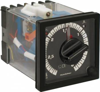
Dold 0027005 time relay delayed return 127V
| Lieske Part No. | 1583487 |
|---|---|
| Mfg Part No | 0027005 |
| EAN-Code | 4030641270056 |
| Manufacturer | Dold |
| Here only | 335,33 EUR
399,04 EUR incl. VAT
|
Further information for Dold 0027005 time relay delayed return 127V
| Technical data | |
| Enclosure design | Front panel mounting |
| Output contacts | 1 C/O contact |
| Time function(s) | Off-delay, with control signal |
| Width | 72 mm |
| Type | EF 7666 |
| Variant | |
| Contact equipping | 1 NO contact undelayed, 1 NO contact delayed, 1 NC contact undelayed, 1 NC contact delayed |
| Nominal voltage | AC 127 V |
| Time range | 0,2 s - 60 h |
Applications
This relay is designed for industrial applications requiring precise, time-controlled switching off. Typical applications include controlling fans, pumps, lighting systems, or other electrical loads that must continue operating for a defined period after the main control is switched off. The front panel mounting form allows easy integration into existing enclosures and control systems. The width of 72 mm corresponds to the standard format for modular units in industrial electrical engineering.
Functions and Equipment in Detail
The device features contact configuration with one instantaneous closer, one delayed closer, one instantaneous opener, and one delayed opener, which corresponds to an output contact type of 1 changeover. The delay time can be adjusted via a continuously variable rotary switch on the front panel within the range of 0.2 s to 60 h. Adjustment is made using an absolute scale with an indicator pointer, enabling precise and repeatable time setting. The repeatability accuracy is ≤ ± 0.5 % of the scale end value, with an exception in the range of 3 s and 6 s, where it is ≤ ± 1 %. The time progression indicator allows visual monitoring of the timing process during operation.
Technology Explained Simply
The timing process is based on a purely mechanical principle, where a clockwork mechanism generates the delay time. This mechanism is independent of electronic components and offers high reliability and long service life. The zero-voltage safety ensures that the relay remains in the switched-off position when the supply voltage is interrupted, which is important for safety in industrial plants. The release time is less than 60 ms, and the contact response time is under 35 ms, enabling rapid reaction to control signals.
Compatibility and Accessories
The relay is designed for operation at a rated frequency of 50/60 Hz and can be operated within a voltage range of 0.8 to 1.1 times the rated voltage. The rated operating voltage is AC 250 V. The contact materials consist of AgNi with a gold plating of 0.2 μm, ensuring high switching durability and corrosion resistance. The electrical service life is at least 100,000 switching operations at 3 A and AC 230 V, and at least 500,000 switching operations at 1 A and AC 230 V. The mechanical service life exceeds 30 million switching operations or over 15,000 operating hours. The maximum fuse rating is 10 A gG/gL.
Mounting and Installation
The relay is mounted in front panel inserts, with the front face measuring 72 mm × 72 mm. The connection terminals are designed for wiring, with terminal markings A1/A2 for operating voltage and B1/B2 for the control signal. Mounting is done by securing to the front panel, meeting the requirements of relevant standards. The front face is protected against spray water and complies with protection class IP 65, allowing use in outdoor or damp environments.
Advantages in Operation
The combination of a wide adjustment range, easy operation, and high repeatability accuracy makes the relay a reliable solution for time-controlled switching operations. The mechanical design ensures long service life and low maintenance. The switching position indicator (except for EH 7666) enables quick visual inspection of the switching state. The IP 65 protection class ensures robust performance under harsh environmental conditions. The time progression indicator supports monitoring of the timing process during operation.
Functions and Equipment in Detail
The device features contact configuration with one instantaneous closer, one delayed closer, one instantaneous opener, and one delayed opener, which corresponds to an output contact type of 1 changeover. The delay time can be adjusted via a continuously variable rotary switch on the front panel within the range of 0.2 s to 60 h. Adjustment is made using an absolute scale with an indicator pointer, enabling precise and repeatable time setting. The repeatability accuracy is ≤ ± 0.5 % of the scale end value, with an exception in the range of 3 s and 6 s, where it is ≤ ± 1 %. The time progression indicator allows visual monitoring of the timing process during operation.
Technology Explained Simply
The timing process is based on a purely mechanical principle, where a clockwork mechanism generates the delay time. This mechanism is independent of electronic components and offers high reliability and long service life. The zero-voltage safety ensures that the relay remains in the switched-off position when the supply voltage is interrupted, which is important for safety in industrial plants. The release time is less than 60 ms, and the contact response time is under 35 ms, enabling rapid reaction to control signals.
Compatibility and Accessories
The relay is designed for operation at a rated frequency of 50/60 Hz and can be operated within a voltage range of 0.8 to 1.1 times the rated voltage. The rated operating voltage is AC 250 V. The contact materials consist of AgNi with a gold plating of 0.2 μm, ensuring high switching durability and corrosion resistance. The electrical service life is at least 100,000 switching operations at 3 A and AC 230 V, and at least 500,000 switching operations at 1 A and AC 230 V. The mechanical service life exceeds 30 million switching operations or over 15,000 operating hours. The maximum fuse rating is 10 A gG/gL.
Mounting and Installation
The relay is mounted in front panel inserts, with the front face measuring 72 mm × 72 mm. The connection terminals are designed for wiring, with terminal markings A1/A2 for operating voltage and B1/B2 for the control signal. Mounting is done by securing to the front panel, meeting the requirements of relevant standards. The front face is protected against spray water and complies with protection class IP 65, allowing use in outdoor or damp environments.
Advantages in Operation
The combination of a wide adjustment range, easy operation, and high repeatability accuracy makes the relay a reliable solution for time-controlled switching operations. The mechanical design ensures long service life and low maintenance. The switching position indicator (except for EH 7666) enables quick visual inspection of the switching state. The IP 65 protection class ensures robust performance under harsh environmental conditions. The time progression indicator supports monitoring of the timing process during operation.

This is an offer of:
79279 Vörstetten
https://industry-electronics.com
Tel. 07666/88499-0
Fax. 07666/88499-111
Diesen Artikel finden Sie unter:
industry-electronics.com/artikel/1583487

Lieske Elektronik e.K.
Reutener Str. 1079279 Vörstetten
https://industry-electronics.com
Tel. 07666/88499-0
Fax. 07666/88499-111
Diesen Artikel finden Sie unter:
industry-electronics.com/artikel/1583487