
Dold 0013214 surge relay EH9997.11 AC220-240V
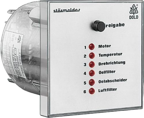
Dold 0013214 surge relay EH9997.11 AC220-240V
| Lieske Part No. | 1153544 |
|---|---|
| Mfg Part No | 0013214 |
| EAN-Code | 4030641132149 |
| Manufacturer | Dold |
| Here only | 360,80 EUR
429,35 EUR incl. VAT
|
Further information for Dold 0013214 surge relay EH9997.11 AC220-240V
| Technical data | |
| Alarm inputs | 6 |
| Alarm inputs extendable up to | 8 |
| Enclosure design | Front panel mounting |
| Operating principle | De-energized on trip |
| Optical signal | LED |
| Width | 96 mm |
| Type | EH 9997 |
| Variant | |
| Contact equipping | 1 changeover contact |
| Nominal voltage | AC 220 - 240 V |
| Signal voltage | 160 - 300 V |
| Variant | De-Energized on trip |
Applications
The EH9997.11 is used for central monitoring of technical systems where multiple fault sources must be detected and visually indicated. Typical application areas include machine monitoring, plant control systems, building automation systems, or industrial processes where rapid detection of errors or failures is required. The integrated function test and acknowledgment button enables simple functionality testing as well as visual and electrical acknowledgment of faults.
Functions and Equipment in Detail
The device features a relay output with a contact configuration of 1 changeover contact, used for collective fault signaling. The contacts are rated for a thermal current of 6 A and meet switching capacity requirements according to AC 15 (make: 2 A / AC 230 V, break: 1 A / AC 230 V). The electrical life expectancy is at least 0.1 million switching operations at 3 A and AC 230 V. The mechanical life expectancy exceeds 30 million switching operations. The release button serves both for acknowledging faults and performing a function test, during which the LEDs and relay output are checked for functionality.
Technology Explained Simply
The device operates on the standby current principle, meaning the output relay is active during normal operation and deactivates when a fault occurs (e.g., voltage loss at the fault alarm input). This allows for clear fault assignment, as the relay is only switched off in the event of a fault. The fault alarm inputs are not galvanically isolated from the power supply, so the terminal A2/N is used jointly for both power supply and fault inputs. For DC voltage, the negative pole must always be connected to A2. Visual indication is provided by LEDs, which remain continuously illuminated when a fault is present.
Compatibility and Accessories
The device is designed for use with voltages in the range of AC/DC 12 to 300 V, with a nominal voltage of AC 220–240 V. For other voltages such as DC 60 V, DC 110 V, or DC 220 V, external resistors are required (e.g., 820 Ω for DC 60 V, 2.2 kΩ for DC 110 V, 4.7 kΩ for DC 220 V). The terminals are rated for conductor cross-sections of 2 x 2.5 mm² (solid) or 2 x 1.5 mm² (stranded wire with sleeve DIN 46228). The tightening torques are 0.8 Nm. Mounting is done using 2 spring clamps with screws.
Mounting and Installation
The EH9997.11 is mounted in front panel form. The front panel opening must have a diameter of 91 mm ±1 mm. The device dimensions are 96 mm (width) x 96 mm (height) x 129 mm (depth). Mounting is done using the included spring clamps and screws. The terminals are equipped with self-lifting connection washers, ensuring a secure and easy connection. The terminals are marked according to EN 50 005.
Advantages in Operation
The device enables central, visual, and electrical monitoring of up to 6 fault sources. The LEDs provide clear visual indication, even under low lighting conditions. The integrated release button simplifies daily use, as acknowledgment and function test can be performed with a single switch. The high mechanical life expectancy and suitability for continuous operation make the device suitable for continuous applications in industrial environments. The protection rating IP 40 for the housing and IP 20 for the terminals provide sufficient protection against mechanical influences and contact. The operating temperature range is between -20 °C and +60 °C, and the storage temperature range is also between -20 °C and +60 °C. The maximum operating altitude is 2000 m above sea level. The EMC requirements according to IEC/EN 61000-4-2 to -4-6 are met, enabling safe operation in electromagnetically noisy environments. Radio frequency interference suppression complies with emission limit class B according to EN 55011.

This is an offer of:
79279 Vörstetten
https://industry-electronics.com
Tel. 07666/88499-0
Fax. 07666/88499-111
Diesen Artikel finden Sie unter:
industry-electronics.com/artikel/1153544

Lieske Elektronik e.K.
Reutener Str. 1079279 Vörstetten
https://industry-electronics.com
Tel. 07666/88499-0
Fax. 07666/88499-111
Diesen Artikel finden Sie unter:
industry-electronics.com/artikel/1153544