
Dold 0010905 time relay delayed-on 115V 0,15S-30H
Industrial Material > Industrial relays and contactors > Industrial Timers
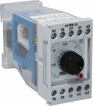
Dold 0010905 time relay delayed-on 115V 0,15S-30H
| Lieske Part No. | 1313006 |
|---|---|
| Mfg Part No | 0010905 |
| EAN-Code | 4030641109059 |
| Manufacturer | Dold |
| Here only | 324,53 EUR
386,19 EUR incl. VAT
|
Further information for Dold 0010905 time relay delayed-on 115V 0,15S-30H
| Technical data | |
| Enclosure design | Switch cabinet |
| Output contacts | 1 C/O contact |
| Time function(s) | On-delay |
| Width | 45 mm |
| Type | AA 7616 |
| Variant | |
| Contact equipping | 1 NC contact delayed, 1 NC contact undelayed, 1 NO contact delayed, 1 NO contact undelayed |
| Nominal voltage | AC 115 V |
| Time range | 0,15 s - 30 h |
| Variant | No-voltage safe |
Applications
This time relay is intended for use in enclosures and is suitable for applications in industrial automation where time-controlled switching sequences are required. Typical applications include controlling pumps, fans, lighting systems, or protecting motors through delayed switching operations. The mounting width of 45 mm allows for compact installation in standard control panels. The rated voltage is AC 115 V, with frequency switching between 50 and 60 Hz, which is performed manually via a slot on the rear of the device using a screwdriver.
Functions and Equipment in Detail
The device features contact configuration with 1 delayed normally open contact, 1 immediate normally open contact, 1 delayed normally closed contact, and 1 immediate normally closed contact, resulting in a total of 1 changeover contact. The delayed contacts switch only after the set time has elapsed, while the immediate contacts switch instantly upon voltage application. The timing ranges are available in six switchable steps, with the current model covering a range of 0.15 seconds to 30 hours. Repeatability is ≤ ± 0.5 %, with an allowable deviation of ≤ ± 1 % in the 3 and 6-second ranges. A timing indicator with a red pointer on the device scale enables visual monitoring of the timing process. An operating position indicator is also integrated, visible when the normally closed contacts are closed (not available on the EH 7616 variant).
Technical Explanation
The timing mechanism is driven by a synchronous motor powered by the control voltage connected to terminals A1-A2. The delay time is achieved through a mechanical timing mechanism with coupling and locking device. In the event of voltage failure, the elapsed time is retained because the coupling is locked by a latch. Upon reapplying voltage, the timing lock is released and the mechanism continues the timing sequence. Adjustment is performed via a stepless rotary switch on the front panel, which selects the timing ranges. The 50/60 Hz frequency switching is done manually on the rear of the device.
Compatibility and Accessories
The device is part of the MINITIMER series and can be combined with other models such as EC 7616, EF 7616, and EH 7616, depending on requirements for mounting width and front panel area. The EF 7616 variant, for example, features a front panel with IP 65 protection, which is splash-proof. The AA 7616 variant, with 45 mm mounting width, is suitable for compact installations. Terminal markings follow standard conventions: A1-A2 for control voltage, B1-B2 for additional control voltage (in voltage failure-safe versions), and contacts 15-16, 27-28, 31-32, 43-44 for the respective normally open and normally closed functions.
Mounting and Installation
The device is mounted in enclosures and requires secure fastening to a suitable mounting plate. The connection terminals are designed for wiring, with the control voltage connected to A1-A2. In voltage failure-safe versions, additional voltage supply to B1-B2 is required to activate the timing function. Frequency switching between 50 and 60 Hz is performed manually on the rear of the device. The delay time is adjusted via the rotary switch on the front panel, with timing ranges selected by switching positions.
Operational Advantages
The wide adjustment range of 0.15 s to 30 h allows flexible adaptation to various requirements. The simple adjustment via the stepless rotary switch reduces installation and commissioning time. The purely mechanical timing control offers high reliability and is independent of electronic components. The voltage failure-safe design ensures safe operation even during short-term power outages. The timing indicator and operating position indicator facilitate maintenance and diagnostics during operation. Compliance with the standard EN 61812-1 ensures conformity with applicable safety and functional requirements for time relays.

This is an offer of:
79279 Vörstetten
https://industry-electronics.com
Tel. 07666/88499-0
Fax. 07666/88499-111
Diesen Artikel finden Sie unter:
industry-electronics.com/artikel/1313006

Lieske Elektronik e.K.
Reutener Str. 1079279 Vörstetten
https://industry-electronics.com
Tel. 07666/88499-0
Fax. 07666/88499-111
Diesen Artikel finden Sie unter:
industry-electronics.com/artikel/1313006