
Dold AI897 insulation monitor 230 V
Industrial Material > Industrial relays and contactors > Switching units / measuring, control relay
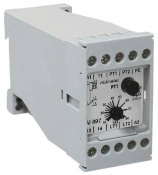
Dold AI897 insulation monitor 230 V
| Lieske Part No. | 305276 |
|---|---|
| Mfg Part No | 0001037 |
| EAN-Code | 4030641010379 |
| Manufacturer | Dold |
| Here only | 279,93 EUR
333,12 EUR incl. VAT
|
Further information for Dold AI897 insulation monitor 230 V
| Technical data | |
| Auxiliary voltage | Without |
| Enclosure design | Switch cabinet |
| IMD type | AC |
| Nominal voltage IT system | AC 24 - 500 V |
| Response value | 10 - 80 kΩ |
| Response value type | Adjustable |
| Width | 45 mm |
| Type | AI 897 |
| Variant | |
| Alarm value | 10 - 80 kOhm |
| Contact equipping | 1 changeover contact |
| Nominal voltage | AC 230 V 45 - 400 Hz |
| Variant | Settable response value |
Applications include monitoring IT networks in industrial plants, medical facilities, or installations requiring high availability, where earth faults must be detected early to prevent damage. The device is designed for use in enclosures and has a width of 45 mm, making it suitable for standard switchboards. The protection rating IP 40 provides protection against contact with fingers and against solid objects, but not against splashing water or dust. The operating temperature ranges from -20 °C to +60 °C, and the storage temperature ranges from -25 °C to +70 °C. The maximum operating altitude is 2000 m above sea level.
Functions and equipment in detail include a 1-changeover contact as the output relay, intended for signaling an insulation fault. The maximum switching voltage is AC 400 V, and the device has a thermal current rating of 6 A. The switching capacity according to AC 15 is 10 A / AC 230 V for make contacts and 5 A / AC 230 V for break contacts. For direct current (DC 13), the switching capacity is 1 A / DC 24 V. The electrical life is at least 300,000 switching operations at 10 A and AC 250 V, and the mechanical life is 30 million switching operations. Short-circuit resistance is ensured by a maximum fuse rating of 5 A gG / gL. The device is designed for continuous operation and consumes approximately 2.5 VA.
Technology explained simply is based on the principle of continuous measurement of insulation resistance between conductors and the protective conductor. When the resistance drops below the set trip threshold, an alarm is triggered. The device operates without auxiliary voltage, simplifying installation. Programming is done via terminals LT1 and LT2: bridging these terminals activates memory behavior, where the fault condition remains stored until manually reset. Without bridging, hysteresis behavior occurs, where the contact switches at the trip threshold and returns when the hysteresis value is exceeded. An external reset button can be connected to LT1-LT2, as well as an external test button to PT1-PT2. The integrated test button PT is used for functional testing of the device.
Compatibility and accessories relate to use in IT systems, where only one insulation monitor per network may be connected. Terminal designations are standardized: A1/A2 for power supply, PE for protective conductor, PT1/PT2 for external test buttons, LT1/LT2 for external reset buttons or programming, and 11/12/14 for the changeover contact. The terminals are designed for mounting in enclosures.
Mounting and installation is carried out in standard switchboards with a width of 45 mm. The terminals are clearly labeled, and the terminal assignment is detailed in the data sheet. Installation requires no auxiliary voltage, simplifying wiring. The terminals are suitable for use with cables meeting electrical requirements.
Operational advantages include high reliability, simple operation, and clear signaling of insulation faults. The device detects faults early, thereby preventing potential damage and increasing operational safety. The continuously adjustable trip threshold allows adaptation to different requirements. The integrated test button and the option for an external reset button enhance maintainability and user-friendliness. Compliance with IEC/EN 61557-8 ensures adherence to international standards.

This is an offer of:
79279 Vörstetten
https://industry-electronics.com
Tel. 07666/88499-0
Fax. 07666/88499-111
Diesen Artikel finden Sie unter:
industry-electronics.com/artikel/305276

Lieske Elektronik e.K.
Reutener Str. 1079279 Vörstetten
https://industry-electronics.com
Tel. 07666/88499-0
Fax. 07666/88499-111
Diesen Artikel finden Sie unter:
industry-electronics.com/artikel/305276