
Dold 0000517 EH9997.11AC/DC24VUS=12-70V surge relay
Industrial Material > Industrial relays and contactors > Switching units / measuring, control relay
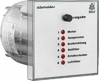
Dold 0000517 EH9997.11AC/DC24VUS=12-70V surge relay
| Lieske Part No. | 525746 |
|---|---|
| Mfg Part No | 0000517 |
| EAN-Code | 4030641005177 |
| Manufacturer | Dold |
| Here only | 378,84 EUR
450,82 EUR incl. VAT
|
Further information for Dold 0000517 EH9997.11AC/DC24VUS=12-70V surge relay
| Technical data | |
| Alarm inputs | 6 |
| Alarm inputs extendable up to | 8 |
| Enclosure design | Front panel mounting |
| Operating principle | De-energized on trip |
| Optical signal | LED |
| Width | 96 mm |
| Type | EH 9997 |
| Variant | |
| Contact equipping | 1 changeover contact |
| Nominal voltage | AC/DC 24 V |
| Signal voltage | 12 - 70 V |
| Variant | De-Energized on trip |
Applications
This device is suitable for monitoring technical systems in industrial plants, production environments, and building technology. It can be used, for example, to indicate faults in pumps, motors, pressure systems, or other monitorable components. The optical indication is provided by LEDs, each assigned to a fault signal input. When a fault is present, the corresponding LED lights up continuously. The fault signal inputs are rated up to AC/DC 300 V, with voltage ranges divided into three sectors: 12–70 V, 70–160 V, and 160–300 V.
Functions and Equipment in Detail
The device features a relay output for collective fault signaling, which is activated when a fault occurs. The contact configuration includes a changeover contact (1 changeover contact), designed for switching operations with a thermal current load of 6 A. The switching capacity complies with IEC/EN 60947-5-1 (AC 15), with the make contact capable of switching up to 2 A at 230 V AC and the break contact up to 1 A at 230 V AC. The electrical life expectancy is 0.1 million switching cycles at 3 A and 230 V AC, while the mechanical life expectancy exceeds 30 million switching cycles.
Technology Explained Simply
The device operates on the standby current principle, meaning the output relay is not activated in the event of a fault. This implies that fault signals are only displayed optically via LEDs, unless the function is modified by removing the rear jumpers X1/X3 to X1/X2, so that faults 5 and 6 are displayed only optically and do not affect the output relay. Power supply is via terminals A1 and A2/N, with fault inputs not isolated from the power supply (common terminal A2/N). For DC voltage, the negative pole must always be connected to A2.
Compatibility and Accessories
The device is suitable for a wide range of fault signals within the voltage range of 12 to 300 V. The terminal clamps are designed for conductor cross-sections of 2 x 2.5 mm² (solid) or 2 x 1.5 mm² (stranded wire with ferrule), with a stripping length of 10 mm. The terminal clamps are secured using flat clamps with self-lifting connection washers.
Mounting and Installation
The device is installed in front panels with a cutout of 91 mm diameter (tolerance +1 mm). Mounting is achieved using two tension clamps with screws. The operating temperature range is -20 °C to +60 °C, and the storage temperature range is also -20 °C to +60 °C. The maximum operating altitude is 2000 m above sea level. The enclosure protection rating is IP 40, and the terminal protection rating is IP 20. The device dimensions are 96 mm (width) x 96 mm (height) x 129 mm (depth). The device is delivered without labeling; individual labeling is available upon request.
Operational Advantages
The optical indication via LEDs allows for quick identification of the fault source. The reset button is used to acknowledge fault signals and perform a function test. The expandability of fault signal inputs from six to eight offers flexibility in system planning. The EMC immunity is specified according to IEC/EN 61000-4-2 to -4-6, including static discharge (8 kV), high-frequency radiation (10 V/m), fast transients (4 kV), and surge voltage (2 kV between supply lines, 4 kV between line and earth). Radio frequency interference suppression complies with Class B limits according to EN 55011. The enclosure is made of thermoplastic with V0 flammability rating according to UL Subject 94. The vibration resistance is 0.35 mm amplitude at frequencies from 10 to 55 Hz.
The device is designed for continuous operation and complies with standards IEC/EN 60947-5-1, IEC/EN 60529, IEC/EN 60068-2-6, and IEC/EN 60068-2-30. Terminal marking follows EN 50 005. The net weight is 300 g. The tightening torques for the terminals are 0.8 Nm.

This is an offer of:
79279 Vörstetten
https://industry-electronics.com
Tel. 07666/88499-0
Fax. 07666/88499-111
Diesen Artikel finden Sie unter:
industry-electronics.com/artikel/525746

Lieske Elektronik e.K.
Reutener Str. 1079279 Vörstetten
https://industry-electronics.com
Tel. 07666/88499-0
Fax. 07666/88499-111
Diesen Artikel finden Sie unter:
industry-electronics.com/artikel/525746