
DEHN 952325 surge arrester 4p TT system
Energy > Surge Protection
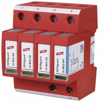
DEHN 952325 surge arrester 4p TT system
| Lieske Part No. | 914345 |
|---|---|
| Mfg Part No | 952325 |
| EAN-Code | 4013364126800 |
| Manufacturer | DEHN |
| Here only | 490,01 EUR
583,11 EUR incl. VAT
|
Further information for DEHN 952325 surge arrester 4p TT system
| Technical data | |
| Energy coordination with terminal equipment (≤ 10 m) | type 2 + type 3 |
| Nominal voltage (a.c.) (UN) | 230 / 400 V (50 / 60 Hz) |
| Max. continuous operating voltage (a.c.) [L-N] (UC) | 320 V (50 / 60 Hz) |
| Max. continuous operating voltage (a.c.) [N-PE] (UC) | 255 V (50 / 60 Hz) |
| Nominal discharge current (8/20 µs) (In) | 20 kA |
| Max. discharge current (8/20 µs) (Imax) | 40 kA |
| Combination wave [L-N] (UOC) | 20 kV |
| Combination wave [N-PE] (UOC) | 6 kV |
| Voltage protection level [L-N]/[N-PE] (UP) | ≤ 1.5 / ≤ 1.5 kV |
| Voltage protection level [L-N]/[N-PE] at 5 kA (UP) | ≤ 1.2 / ≤ 1.5 kV |
| Protective conductor current (IPE) | ≤ 10 µA |
| Response time [L-N] (tA) | ≤ 25 ns |
| Response time [N-PE] (tA) | ≤ 100 ns |
| Max. mains-side overcurrent protection | 125 A gG |
| Short-circuit withstand capability for max. mains-side overcurrent protection (ISCCR) | 25 kArms |
| Temporary overvoltage (TOV) [L-N] (UT) – Characteristic | 335 V / 5 sec. – Festigkeit, 440 V / 120 min. – sicherer Ausfall |
| Temporary overvoltage (TOV) [N-PE] (UT) - Characteristic | 1200 V / 200 ms – withstand |
| Operating temperature range (TU) | -40 °C ... +80 °C |
| Operating state / fault indication | green / red |
| Number of ports | 1 |
| Cross-sectional area (min.) | 1.5 mm2 solid / flexible |
| Cross-sectional area (max.) | 35 mm2 stranded / 25 mm2 flexible |
| For mounting on | 35 mm DIN rails acc. to EN 60715 |
| Enclosure material | thermoplastic, red, UL 94 V-0 |
| Place of installation | indoor installation |
| Degree of protection | IP 20 (integrated) |
| Capacity | 4 Standard DIN module, DIN 43880 |
| Approvals | DEKRA |
| Type of remote signalling contact | changeover contact |
| Switching capacity (a.c.) | 250 V / 0.5 A |
| Switching capacity (d.c.) | 250 V / 0.1 A; 125 V / 0.2 A; 75 V / 0.5 A |
| Cross-sectional area for remote signalling terminals | max. 1.5 mm2 solid / flexible |
Applications
The arrester is intended for use in the lightning protection zone concept at interfaces 0B - 1 and higher. It protects electrical installations in indoor environments against overvoltages caused by direct or indirect lightning strikes, network disturbances, or switching operations. The application is in low-voltage installations with a nominal voltage of 230/400 V (50/60 Hz) and a maximum voltage of 320 V [L-N] or 255 V [N-PE].
Functions and Equipment in Detail
The device features surge arrester monitoring with Thermo-Dynamic-Control, ensuring high device safety. The operational and fault indication is provided via a green or red LED, allowing visual inspection of the operating status. In case of arrester failure, the circuit is opened (OCM), ensuring safe protection of downstream devices. A potential-free remote signaling contact (changeover) enables integration into monitoring systems; it has a switching capacity of 250 V / 0.5 A (AC) and is designed for connection cross-sections up to 1.5 mm², single- or multi-strand.
Technology Explained Simply
The arrester uses zinc oxide varistors and spark gaps to divert overvoltages. The nominal discharge current is 20 kA (8/20 µs), with a maximum discharge current of 40 kA. The protection level is ≤ 1.5 kV [L-N]/[N-PE] and ≤ 1.75 kV [L-PE], with the [L-N] protection level dropping to ≤ 1.2 kV at a test current of 5 kA. The response time is ≤ 25 ns [L-N] and ≤ 100 ns [N-PE], enabling rapid reaction to overvoltages. The TOV voltage [L-N] is 335 V for 5 seconds (withstand) and 440 V for 120 minutes (safe failure), while [N-PE] can withstand 1200 V for 200 ms. The short-circuit withstand is 25 kAeff with a maximum network-side overcurrent protection of 125 A gG.
Compatibility and Accessories
The arrester is designed for TT- and TN-S systems and can be used energy-coordinated within the Red/Line product family. Installation is on a 35 mm DIN rail according to EN 60715. Connection cross-sections range from 1.5 mm² (min.) to 35 mm² (max.) for multi-strand conductors and 25 mm² for fine-strand conductors. The insulation between main and auxiliary circuits is double, with the overvoltage category of the main circuit being III and that of the auxiliary circuit II.
Installation and Mounting
The unit is mounted indoors and has an installation width of 4 TE according to DIN 43880. The housing is made of red thermoplastic (UL 94 V-0) and is designed for use at temperatures from -40 °C to +80 °C. The protection rating is IP 20 (installed), providing protection against finger contact and solid foreign objects. Mounting is tool-free, with module locking systems enabling easy replacement of protection modules.
Operational Advantages
The combination of high discharge capacity, fast response time, and integrated monitoring with fault indication ensures reliable protection. The modular design allows flexible adaptation to different system configurations. Integration into monitoring systems via the remote signaling contact enables proactive fault detection. Certifications by DEKRA, UKCA, CE, and UL confirm compliance with European and international safety standards.

This is an offer of:
79279 Vörstetten
https://industry-electronics.com
Tel. 07666/88499-0
Fax. 07666/88499-111
Diesen Artikel finden Sie unter:
industry-electronics.com/artikel/914345

Lieske Elektronik e.K.
Reutener Str. 1079279 Vörstetten
https://industry-electronics.com
Tel. 07666/88499-0
Fax. 07666/88499-111
Diesen Artikel finden Sie unter:
industry-electronics.com/artikel/914345