
DEHN 785637 SE REG 3TE Locking Element 3TE
Energy > Surge Protection
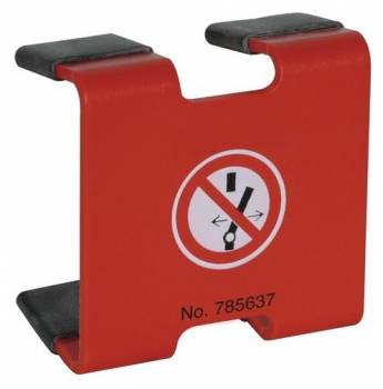
DEHN 785637 SE REG 3TE Locking Element 3TE
| Lieske Part No. | 930461 |
|---|---|
| Mfg Part No | 785637 |
| EAN-Code | 4013364100701 |
| Manufacturer | DEHN |
| Here only | 33,73 EUR
40,14 EUR incl. VAT
|
Further information for DEHN 785637 SE REG 3TE Locking Element 3TE
| General | |
| Norm | DIN 40008 |
| Safety marking | Do not switch |
| Regulation | VBG 125 |
| Terminal dimension | 45 mm |
| Size | 3 modular widths |
| Nominal voltage | 1000 V |
| Dimensions | 52 x 51 mm |
Applications
The lock element is used in electrical installations where safe disconnection and locking of switches is required to prevent accidents or incorrect operation. Typical applications include maintenance work, inspections, or servicing of electrical equipment, where the power supply must be permanently interrupted and secured. It is particularly suitable for row-mounted devices installed in enclosures or distribution boards. Its use in installations with nominal voltages up to 1000 V makes it suitable for industrial, commercial, and municipal electrical installations.
Functions and Equipment in Detail
The lock element prevents mechanical operation of the switch by engaging with the switch mechanism and blocking its movement. It is designed for switches with a terminal spacing of 45 mm, enabling universal use in many standard switch types. The printed marking “Do not switch” serves as a visual warning and meets the requirements of VBG 125, which mandates clear identification of locked equipment. The size of 3 TE allows compact installation in switchboards and fits standard enclosure dimensions.
Technology Explained Simply
The technology of the lock element is based on a mechanical blocking mechanism that engages with the operating mechanism of the LS switch. The lock is inserted into the switch and prevents it from being moved into the ON position. DIN 40008 defines the requirements for the construction and use of lock elements to ensure uniform and safe handling. The “Do not switch” marking is a visual indicator that emphasizes the locking function and supports compliance with safety regulations. The maximum nominal voltage of 1000 V defines its application range in low-voltage installations.
Compatibility and Accessories
The lock element is compatible with single- and multi-pole LS switches featuring a terminal spacing of 45 mm. It is designed for installation in row-mounted devices installed in enclosures or distribution boards. The size of 3 TE enables integration into standard switchboards.
Installation and Mounting
Installation is carried out by inserting the lock element into the switch, where the mechanical blocking prevents operation. No additional tools or components are required. The lock is inserted directly into the switch, with the fit ensuring compatibility with a terminal spacing of 45 mm. The visual marking “Do not switch” is already integrated into the lock element and requires no additional labeling.
Operational Advantages
The lock element provides a reliable mechanical locking function that prevents accidental re-energizing. Compliance with DIN 40008 and VBG 125 ensures conforming and safe application. The visual marking supports safety regulation compliance and improves operational transparency. The universal fit for switches with 45 mm terminal spacing and the size of 3 TE enable flexible use in various installations.

This is an offer of:
79279 Vörstetten
https://industry-electronics.com
Tel. 07666/88499-0
Fax. 07666/88499-111
Diesen Artikel finden Sie unter:
industry-electronics.com/artikel/930461

Lieske Elektronik e.K.
Reutener Str. 1079279 Vörstetten
https://industry-electronics.com
Tel. 07666/88499-0
Fax. 07666/88499-111
Diesen Artikel finden Sie unter:
industry-electronics.com/artikel/930461