
Siemens 6SL3201-0BE21-0AA0 brake resistor R=140 Ohm
Industrial Material > Engines and accessories
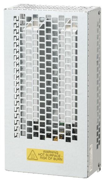
Siemens 6SL3201-0BE21-0AA0 brake resistor R=140 Ohm
| Lieske Part No. | 365130 |
|---|---|
| Mfg Part No | 6SL32010BE210AA0 |
| EAN-Code | 4042948660195 |
| Manufacturer | Siemens |
| Here only | 173,17 EUR
206,07 EUR incl. VAT
|
Further information for Siemens 6SL3201-0BE21-0AA0 brake resistor R=140 Ohm
| General | |
| Resistance | 140 Ohm |
| Continuous power | 200 W |
| Maximum power | 4000 W |
| Maximum duty cycle | 12 s |
| Duty cycle (ED) | 5 % |
| Operation mode | stand-alone |
Applications
The brake resistor is designed for drive systems in which electrical energy flows back into the converter during braking operations or downward load movements. This regenerative energy must be dissipated to prevent overvoltage in the DC link. Applications include conveyor systems, presses, crane systems, or machines with high dynamics, where frequent starting and braking occur. The stand-alone module design enables flexible installation outside the converter, optimizing heat dissipation and simplifying installation in existing systems.
Functions and Equipment in Detail
The resistor has a nominal resistance of 140 Ohm, defining the electrical load in the system. The continuous power rating is 200 W, meaning the resistor can be continuously loaded with this power without exceeding temperature limits. The maximum power is 4000 W, which is permissible for up to 12 seconds with a duty cycle of 5 %. This specific load profile definition (ED = duty cycle) enables targeted use during short-term, high-intensity braking operations. The stand-alone module construction allows independent mounting and maintenance, facilitating integration into existing systems.
Technology Explained Simply
The brake resistor operates on the principle of resistive braking: during regenerative braking, the kinetic energy of the load is converted into electrical energy, which is then dissipated as heat through the resistor. The resistance values and power ratings are dimensioned to ensure thermal stress on the component remains within permissible limits. The specification P_max=4000W/12s/5% ED means the resistor can be briefly loaded with 4000 W, provided the total duty cycle per cycle does not exceed 5 % and the maximum duration per switching event is 12 seconds. The continuous power rating of 200 W is designed for continuous operating conditions. Heat dissipation occurs via the surface of the resistor body, requiring sufficient air circulation and clearance from other components.
Compatibility and Accessories
The brake resistor is specifically developed for use with frequency converters from the SINAMICS series. It is connected as an external module and is not part of the converter. Connection is made via designated terminal clamps, with electrical parameters (resistance, power) matched to the requirements of the respective drive system. Installation is typically carried out at a suitable, well-ventilated location, away from other heat sources.
Mounting and Installation
Installation is typically performed on a fixed, non-combustible base, ensuring sufficient cooling. Electrical connections are made via designated terminals, observing polarity and maximum permissible current. Connecting cables must be dimensioned according to the electrical load.
Advantages in Operation
Using the brake resistor enables reliable and safe braking in drive systems, especially with loads having high kinetic energy. The defined power output and clear specification of duty cycle ensure predictable thermal stress. The stand-alone module design simplifies maintenance and replaceability, increasing system uptime. Use with SINAMICS converters ensures optimal compatibility and control of the braking process.

This is an offer of:
79279 Vörstetten
https://industry-electronics.com
Tel. 07666/88499-0
Fax. 07666/88499-111
Diesen Artikel finden Sie unter:
industry-electronics.com/artikel/365130

Lieske Elektronik e.K.
Reutener Str. 1079279 Vörstetten
https://industry-electronics.com
Tel. 07666/88499-0
Fax. 07666/88499-111
Diesen Artikel finden Sie unter:
industry-electronics.com/artikel/365130