Siemens 5WG1141-1AB21 - KNX / DALI Gateway TWIN DALI ballasts
Installation > Home Automation > EIB material
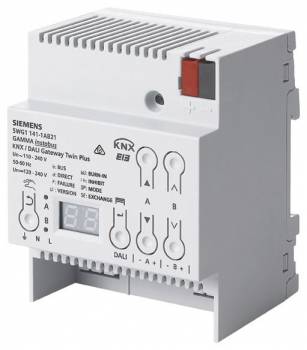
Siemens 5WG1141-1AB21 - KNX / DALI Gateway TWIN DALI ballasts
| Lieske Part No. | 368932 |
|---|---|
| Mfg Part No | 5WG11411AB21 |
| EAN-Code | 4001869471426 |
| Manufacturer | Siemens |
| Here only | 1.019,70 EUR
1.213,44 EUR incl. VAT
|
Further information for Siemens 5WG1141-1AB21 - KNX / DALI Gateway TWIN DALI ballasts
- Two DALI outputs in accordance with IEC 62386-101 and 103, up to 64 DALI-EVG Ed.1 and DALI-2 and at least 10 DALI sensors can be connected via DALI bus line
- Integrated power supply unit for input voltage of AC 110-240 V, 50-60 Hz or DC 120-240 V to supply power to the gateway electronics and DALI outputs
- DALI output voltage approx. 19 V, potential-free and short-circuit-proof
- External voltage detection during commissioning to indicate whether there is faulty mains voltage at the DALI output
- LED display to display operating states and error messages
- 1 button to switch between bus and direct operation
- 1 pair of buttons per DALI output to switch all connected lights on or off together in direct operation
- 1 LED per DALI output for Switching status display of all connected lights in direct operation
- Distribution of the max. 64 DALI ECGs per channel into max. 16 DALI groups per channel, which can be controlled in groups or individually (switching, dimming, dimming value) and report status and lamp failure
- Support of DALI DT8 for color temperature control (Tunable White). Individual, group, scene, effect and schedule control for human centric lighting
- Configurable behavior in the event of a bus voltage failure (standalone)
- Configurable standard applications without ETS
- Parameterizable burn-in function for all electronic ballasts via control buttons and individually via object
- Time switch function for day, week, date, with astro function
- Control of all connected lights together in broadcast mode
- Reporting and display of a lamp and electronic ballast error per lighting group and per DALI participant
- Implementation of dimming commands in temporary setpoint shifts for electronic ballasts with integrated constant light control and directly connected brightness sensor
- One or two-stage time switch operation
- 4 integrated effect controls for one-off or cyclical running light or color effects
- Differentiation of single-battery emergency lights with one or two DALI devices
- Starting the self-tests of each individual converter and reporting the test result via bus or saving in persistent memory with memory monitoring via object
- Differentiation between functional test, partial duration test, duration test
- Configuration option for all electronic ballasts in emergency operation to a defined Dimming value to be accepted
- Blocking of switching and dimming commands and configuration when emergency operation is activated via bus
- Activation of emergency operation if a configurable number of electronic ballasts fail
- Blocking object to suppress error messages when the electronic ballast is disconnected during emergency lighting testing
- Blocking of battery operation of self-contained emergency lights via control buttons
- Up to 6 standby area evaluations per channel for controlling switching actuators
- Integrated scene control for up to 16 scenes per channel
- 16 integrated 2-point controllers for brightness control and 16 constant light controllers for 1 main lighting row and up to 4 additional lighting rows
- CIN for clear assignment of the DALI electronic ballast
- Replace defective DALI electronic ballasts without ETS
- Assignment of the electronic ballast to the individual groups and with the option of testing the electronic ballasts, groups, scenes and effects using ETS
- Assignment of DALI sensors using ETS
- Integrated KNX bus coupler with max. half the standard bus load, KNX bus connection via bus terminal
- Modular device for mounting on TH35 DIN rail EN60715

This is an offer of:
79279 Vörstetten
https://industry-electronics.com
Tel. 07666/88499-0
Fax. 07666/88499-111
Diesen Artikel finden Sie unter:
industry-electronics.com/artikel/368932

Lieske Elektronik e.K.
Reutener Str. 1079279 Vörstetten
https://industry-electronics.com
Tel. 07666/88499-0
Fax. 07666/88499-111
Diesen Artikel finden Sie unter:
industry-electronics.com/artikel/368932