
Siemens 3RH19211DA11 Auxiliary Switch 1S 1Ö Screw Terminal
Industrial Material > Industrial relays and contactors > Contactors
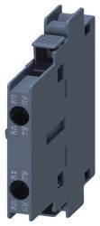
Siemens 3RH19211DA11 Auxiliary Switch 1S 1Ö Screw Terminal
| Lieske Part No. | 802846 |
|---|---|
| Mfg Part No | 3RH19211DA11 |
| EAN-Code | 4011209379862 |
| Manufacturer | Siemens |
| Here only | 18,11 EUR
21,55 EUR incl. VAT
|
Further information for Siemens 3RH19211DA11 Auxiliary Switch 1S 1Ö Screw Terminal
| General | |
| Connection type | Screw connection |
| Contact arrangement | 1 normally open contact (NO) + 1 normally closed contact (NC) |
| Mounting method | Sideways |
| Compatibility | for contactors 3RT1, sizes S0-S12 |
| System | SIRIUS |
| Norm | DIN EN 50012 |
| Function | Forced-guided contacts |
Applications
The auxiliary switch 3RH1921-1DA11 is used in industrial control systems where additional contacts are required for signals, status monitoring, or feedback to control devices. It is particularly suitable for applications in manufacturing automation, machine building, and plant control, where reliability and quick installation are important. The side mounting allows for a compact arrangement alongside the power contactor, saving space in the enclosure.
Functions and Equipment in Detail
The auxiliary switch provides an instant-acting normally open contact and an instant-acting normally closed contact, which are mechanically linked to the main contact of the contactor. This means the auxiliary switch operates exactly in sync with the main contact of the contactor, which is crucial for precise signal transmission in control circuits. The contacts are designed for use in control circuits, with exact current and voltage limits to be determined from the technical data of the specific application. The screw terminal variant ensures a secure and mechanically stable connection, suitable for industrial environments.
Technology Explained Simply
The mechanical linkage of the contacts ensures that the auxiliary switch operates exactly in sync with the main contact of the contactor — opening or closing simultaneously. This is important to ensure that signals such as “contactor switched on” or “contactor switched off” are transmitted at the exact right time. The side mounting is tool-free, reducing installation time and simplifying maintenance. The screw terminals provide a robust connection that remains stable even under vibration and mechanical stress.
Compatibility and Accessories
The auxiliary switch 3RH1921-1DA11 is specifically designed for power contactors of the 3RT1 series in sizes S0 to S12. It is part of the SIRIUS system and can be combined with other auxiliary switch modules such as the 3RH1921-2DA11 (1S+1Oe, Cage Clamp) or the 3RH2921-1DA11 (1S+1Oe, busbars) to support different connection types and mounting variants. These modules allow flexible adaptation to various enclosure configurations and connection requirements.
Mounting and Installation
Mounting is performed on the side of the 3RT1 power contactor without tools. The contactor size must be within the range S0 to S12 to ensure mechanical compatibility. The screw terminals are connected using appropriate tools (e.g. screwdriver). The electrical connection is made in the control circuit, with maximum permissible current and voltage values to be determined from the technical data of the specific application. Mounting is simple and requires no special tools or additional components.
Advantages in Operation
The auxiliary switch 3RH1921-1DA11 offers reliable and fast expansion of control functions. The tool-free mounting reduces installation time and simplifies maintenance and replacement. The mechanical linkage of the contacts ensures precise signal transmission, which is essential for control system functionality. Use within the SIRIUS system ensures high compatibility with other modules and enables modular, scalable system design.
Standards and Regulations
The auxiliary switch complies with DIN EN 50012, which defines requirements for auxiliary switches in electrical control systems. This standard specifies, among other things, the electrical and mechanical requirements for contacts, switching capacity, and service life. Compliance with this standard ensures reliability and safety in industrial applications.

This is an offer of:
79279 Vörstetten
https://industry-electronics.com
Tel. 07666/88499-0
Fax. 07666/88499-111
Diesen Artikel finden Sie unter:
industry-electronics.com/artikel/802846

Lieske Elektronik e.K.
Reutener Str. 1079279 Vörstetten
https://industry-electronics.com
Tel. 07666/88499-0
Fax. 07666/88499-111
Diesen Artikel finden Sie unter:
industry-electronics.com/artikel/802846