
Schneider Electric ZB4BZ102 Auxiliary Switch Block 1NO Metal
Industrial Material > Control devices / Pilot devices > Built-Command and signaling devices
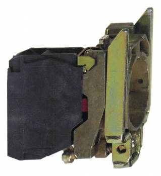
Schneider Electric ZB4BZ102 Auxiliary Switch Block 1NO Metal
| Lieske Part No. | 911927 |
|---|---|
| Mfg Part No | ZB4BZ102 |
| EAN-Code | 3389110889383 |
| Manufacturer | Schneider Electric |
| Here only | 10,45 EUR
12,44 EUR incl. VAT
|
Further information for Schneider Electric ZB4BZ102 Auxiliary Switch Block 1NO Metal
| Complementary | |
| CAD overall width | 30 mm |
| CAD overall height | 47 mm |
| CAD overall depth | 37 mm |
| Terminals description ISO n°1 | (11-12)NC |
| Net weight | 0.053 kg |
| Contacts usage | Standard contacts |
| Positive opening | With conforming to IEC 60947-5-1 appendix K |
| Operating travel | 1.5 mm (NC changing electrical state); 4.3 mm (total travel) |
| Operating force | 2 N NC changing electrical state |
| Mechanical durability | 5000000 cycles |
| Tightening torque | 0.8…1.2 N.m conforming to IEC 60947-1 |
| Shape of screw head | Cross compatible with Philips no 1 screwdriver; Cross compatible with pozidriv No 1 screwdriver; Slotted compatible with flat Ø 4 mm screwdriver; Slotted compatible with flat Ø 5.5 mm screwdriver |
| Contacts material | Silver alloy (Ag/Ni) |
| Short-circuit protection | 10 A cartridge fuse type gG conforming to IEC 60947-5-1 |
| [Ith] conventional free air thermal current | 10 A conforming to IEC 60947-5-1 |
| [Ui] rated insulation voltage | 600 V (pollution degree 3) conforming to IEC 60947-1 |
| [Uimp] rated impulse withstand voltage | 6 kV conforming to IEC 60947-1 |
| [Ie] rated operational current | 3 A at 240 V, AC-15, A600 conforming to IEC 60947-5-1; 6 A at 120 V, AC-15, A600 conforming to IEC 60947-5-1; 0.1 A at 600 V, DC-13, Q600 conforming to IEC 60947-5-1; 0.27 A at 250 V, DC-13, Q600 conforming to IEC 60947-5-1; 0.55 A at 125 V, DC-13, Q600 conforming to IEC 60947-5-1; 1.2 A at 600 V, AC-15, A600 conforming to IEC 60947-5-1 |
| Electrical durability | 10000000 cycles, AC-15, 2 A at 230 V, operating rate |
| Electrical reliability | Λ < 10exp(-6) at 5 V, 1 mA in clean environment conforming to IEC 60947-5-4; Λ < 10exp(-8) at 17 V, 5 mA in clean environment conforming to IEC 60947-5-4 |
| Device presentation | Basic sub-assemblies |
| Contractual warranty | |
| Warranty (in months) | 18 |
| Environment | |
| Protective treatment | TH |
| Ambient air temperature for storage | -40…70 °C |
| Ambient air temperature for operation | -40…70 °C |
| IP degree of protection | IP20 conforming to IEC 60529 |
| Standards | CSA C22.2 No 14; IEC 60947-5-5; IEC 60947-5-1; UL 508; JIS C8201-5-1; IEC 60947-1; IEC 60947-5-4; JIS C8201-1 |
| Product certifications | BV; UL; CSA; DNV; LROS (Lloyds register of shipping) |
| Vibration resistance | 5 gn (f= 2…500 Hz) conforming to IEC 60068-2-6 |
| Shock resistance | 30 gn (duration = 18 ms) for half sine wave acceleration conforming to IEC 60068-2-27; 50 gn (duration = 11 ms) for half sine wave acceleration conforming to IEC 60068-2-27 |
| Logistical informations | |
| Country of origin | FR |
| Main | |
| Range of product | Harmony XB4 |
| Product or component type | Complete body/contact assembly |
| Device short name | ZB4 |
| Fixing collar material | Zamak |
| Sale per indivisible quantity | 1 |
| Head type | Standard |
| Contacts type and composition | 1 NC |
| Contact operation | Slow-break |
| Contact block type | Single |
| Device composition | Body; Fixing collar |
| Connections - terminals | Screw clamp terminals, = 1 x 0.22 mm² without cable end conforming to IEC 60947-1 |
| Packing Units | |
| Unit Type of Package 1 | PCE |
| Number of Units in Package 1 | 1 |
| Package 1 Height | 4.400 cm |
| Package 1 Width | 3.400 cm |
| Package 1 Length | 5.400 cm |
| Package 1 Weight | 52.000 g |
| Unit Type of Package 2 | S03 |
| Number of Units in Package 2 | 200 |
| Package 2 Height | 30.000 cm |
| Package 2 Width | 30.000 cm |
| Package 2 Length | 40.000 cm |
| Package 2 Weight | 10.920 kg |
| Unit Type of Package 3 | P06 |
| Number of Units in Package 3 | 1600 |
| Package 3 Height | 75.000 cm |
| Package 3 Width | 60.000 cm |
| Package 3 Length | 80.000 cm |
| Package 3 Weight | 97.116 kg |
Applications
The auxiliary switch block is suitable for use in industrial plants, machine controls, and building automation systems. It is frequently used in combination with pushbuttons, signal lamps, or selector switches to implement additional switching functions. Compatibility with 22 mm and 30 mm devices from the Harmony XB4/ZB4 series enables flexible integration into existing systems. The assembly is designed for use in environments with high mechanical stress, as evidenced by its high vibration resistance (5 gn at 2–500 Hz) and shock resistance (30 gn and 50 gn depending on duration). The operating temperature ranges from -40 °C to +70 °C, enabling use in climatically demanding environments.
Functions and Equipment in Detail
The contact block is designed as a single-pole contact and provides positive opening, meeting the requirements of IEC 60947-5-1, Annex K. The contact material consists of a silver alloy (Ag/Ni), ensuring high electrical conductivity and corrosion resistance. The mechanical life is 5,000,000 cycles, and the electrical life is 10,000,000 cycles under AC-15 operation at 2 A and 230 V. The actuation force is 2 N, the operating stroke is 1.5 mm (normally open, alternating electrical state), and the total stroke is 4.3 mm. The screw head shape is compatible with Phillips No. 1, position No. 1, as well as flat screwdrivers with Ø 4 mm and Ø 5.5 mm. The tightening torque is between 0.8 and 1.2 Nm.
Technology Explained Simply
The screw terminals enable a secure and durable connection with conductors. The rated insulation voltage is 600 V (pollution degree 3), and the rated impulse voltage withstand is 6 kV, ensuring high electrical safety. The conventional thermal current (Ith) is 10 A in free air. The rated operating currents are defined according to switching type and voltage: 3 A at 240 V (AC-15), 6 A at 120 V (AC-15), 0.1 A at 600 V (DC-13), 0.27 A at 250 V (DC-13), 0.55 A at 125 V (DC-13), and 1.2 A at 600 V (AC-15). Electrical reliability is specified according to IEC 60947-5-4, with failure rate (Λ) below 10⁻⁶ at 5 V/1 mA and below 10⁻⁸ at 17 V/5 mA.
Compatibility and Accessories
The auxiliary switch block is compatible with 22 mm and 30 mm devices from the Harmony XB4/ZB4 series. Suitable accessories include labeling fields such as ZBYLEG201001, label holders such as ZBZ32 or ZBZ33, and empty housings such as XAPD1201. These elements allow for individual labeling and integration into existing control panels. The assembly is designed for use in enclosures and can be combined with other components from the series.
Mounting and Installation
Mounting is done using integrated mounting flanges, ensuring secure and vibration-resistant anchoring. The screw terminals are designed for cable cross-sections from 0.22 mm² and require a tightening torque of 0.8 to 1.2 Nm. The screw head shape is compatible with various screwdrivers, providing flexible installation. The assembly is designed for use in enclosures with protection rating IP20, which protects against finger contact and against solid foreign objects up to 12.5 mm in diameter.
Operational Advantages
The high mechanical and electrical life, robust construction from Zamak, and high vibration resistance ensure reliable performance over long periods. The wide temperature resistance from -40 °C to +70 °C enables use in various environments. Compliance with international standards such as IEC 60947-5-1, UL 508, CSA C22.2 No. 14, and JIS C8201-1, as well as certifications by BV, UL, CSA, and DNV, guarantee quality and worldwide applicability. The assembly carries the Green Premium environmental label, providing information on material contents and circular economy.
Protection Rating and Environmental Conditions
The protection rating IP20 corresponds to IEC 60529 and protects against finger contact and against solid foreign objects up to 12.5 mm. The ambient temperature for operation and storage ranges from -40 °C to +70 °C. The assembly is designed for indoor use, as IP20 does not provide protection against moisture or splashing water. Mounting is achieved via a Zamak holding flange, ensuring high mechanical stability.
Certifications and Standards
The auxiliary switch block complies with standards IEC 60947-5-5, IEC 60947-5-1, IEC 60947-1, IEC 60947-5-4, CSA C22.2 No. 14, UL 508, JIS C8201-5-1, and JIS C8201-1. Product certifications include BV, UL, CSA, and DNV. These certifications guarantee compliance with international safety and quality standards and enable use in various global markets.
Dimensions and Weight
The CAD overall dimensions are 30 mm (width), 47 mm (height), and 37 mm (depth). The product weight is 0.053 kg. The dimensions are designed for mounting in standard enclosures and allow compact integration into existing systems.
Short-Circuit Protection
The auxiliary switch block is equipped with short-circuit protection requiring a 10 A fuse cartridge type gG, according to IEC 60947-5-1. This ensures safe operation and protects the electrical installation against overloads.
Practical Application
In industrial automation, the auxiliary switch block is frequently used to implement auxiliary circuits, status indication, or control of auxiliary functions. The modular design allows flexible adaptation to individual requirements. The high reliability and long life reduce maintenance and replacement intervals, increasing operational safety.

This is an offer of:
79279 Vörstetten
https://industry-electronics.com
Tel. 07666/88499-0
Fax. 07666/88499-111
Diesen Artikel finden Sie unter:
industry-electronics.com/artikel/911927

Lieske Elektronik e.K.
Reutener Str. 1079279 Vörstetten
https://industry-electronics.com
Tel. 07666/88499-0
Fax. 07666/88499-111
Diesen Artikel finden Sie unter:
industry-electronics.com/artikel/911927