
Schneider Electric LP4K09004BW3 contactor 4-pole 9A 24 V DC
Industrial Material > Industrial relays and contactors > Contactors
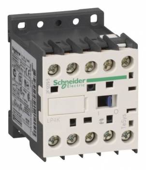
Schneider Electric LP4K09004BW3 contactor 4-pole 9A 24 V DC
| Lieske Part No. | 366466 |
|---|---|
| Mfg Part No | LP4K09004BW3 |
| EAN-Code | 3389110498646 |
| Manufacturer | Schneider Electric |
| Here only | 65,52 EUR
77,97 EUR incl. VAT
|
Further information for Schneider Electric LP4K09004BW3 contactor 4-pole 9A 24 V DC
| Complementary | |
| Utilisation category | AC-1 |
| Poles description | 4P |
| power pole contact composition | 4 NO |
| [Ue] rated operational voltage | Power circuit: |
| [Ie] rated operational current | 20 A (at |
| Control circuit type | DC wide range |
| [Uc] control circuit voltage | 24 V DC |
| [Uimp] rated impulse withstand voltage | 8 kV |
| Overvoltage category | III |
| [Ith] conventional free air thermal current | 20 A (at 60 °C) for power circuit; 10 A (at 50 °C) for signalling circuit |
| Irms rated making capacity | 110 A AC for power circuit conforming to IEC 60947 |
| Rated breaking capacity | 110 A at 220...230 V conforming to IEC 60947; 110 A at 380...400 V conforming to IEC 60947; 110 A at 415 V conforming to IEC 60947; 110 A at 440 V conforming to IEC 60947; 80 A at 500 V conforming to IEC 60947; 70 A at 660...690 V conforming to IEC 60947 |
| [Icw] rated short-time withstand current | 90 A 50 °C - 1 s for power circuit; 85 A 50 °C - 5 s for power circuit; 80 A 50 °C - 10 s for power circuit; 60 A 50 °C - 30 s for power circuit; 45 A 50 °C - 1 min for power circuit; 40 A 50 °C - 3 min for power circuit; 20 A 50 °C - >= 15 min for power circuit |
| Associated fuse rating | 25 A gG at |
| Average impedance | 3 mOhm - Ith 20 A 50 Hz for power circuit |
| [Ui] rated insulation voltage | Power circuit: 600 V conforming to UL 508; Power circuit: 690 V conforming to IEC 60947-4-1; Power circuit: 600 V conforming to CSA C22.2 No 14 |
| Inrush power in W | 1.8 W (at 20 °C) |
| Hold-in power consumption in W | 1.8 W at 20 °C |
| Heat dissipation | 1.8 W |
| Control circuit voltage limits | Operational: 0.7...1.3 Uc (at = 0.10 Uc (at |
| Connections - terminals | Screw clamp terminals 1 cable(s) 1.5…4 mm²solid; Screw clamp terminals 1 cable(s) 0.75…4 mm²flexible without cable end; Screw clamp terminals 1 cable(s) 0.34…2.5 mm²flexible with cable end; Screw clamp terminals 2 cable(s) 1.5…4 mm²solid; Screw clamp terminals 2 cable(s) 0.75…4 mm²flexible without cable end; Screw clamp terminals 2 cable(s) 0.34…1.5 mm²flexible with cable end; Power circuit: screw clamp terminals 2 cable(s) 1.5 mm²flexible with cable end |
| Maximum operating rate | 3600 cyc/h |
| Coil technology | With integral suppression device |
| Mounting support | Plate; Rail |
| Tightening torque | 0.8…1.3 N.m - on screw clamp terminals Philips No 2; 0.8…1.3 N.m - on screw clamp terminals flat Ø 6 mm; 0.8…1.3 N.m - on screw clamp terminals pozidriv No 2 |
| Operating time | 30...40 ms coil energisation and NO closing; 10 ms coil de-energisation and NO opening |
| Safety reliability level | B10d = 1369863 cycles contactor with nominal load conforming to EN/ISO 13849-1; B10d = 20000000 cycles contactor with mechanical load conforming to EN/ISO 13849-1 |
| Mechanical durability | 30 Mcycles |
| Electrical durability | 0.16 Mcycles 20 A AC-1 at Ue |
| Height | 58 mm |
| Width | 45 mm |
| Depth | 57 mm |
| Net weight | 0.235 kg |
| Contractual warranty | |
| Warranty (in months) | 18 |
| Environment | |
| Standards | EN/IEC 60947-4-1; EN/IEC 60947-5-1; UL 60947-4-1; UL 60947-5-1; CSA C22.2 No 60947-4-1; CSA C22.2 No 60947-5-1; GB/T 14048.4 |
| Product certifications | CB Scheme; CCC; UL; CSA; EAC; CE; UKCA |
| IP degree of protection | IP2X |
| Ambient air temperature for operation | -25…50 °C |
| Ambient air temperature for storage | -50…80 °C |
| Operating altitude | 2000 m without derating |
| Flame retardance | V1 conforming to UL 94; Requirement 2 conforming to NF F 16-101; Requirement 2 conforming to NF F 16-102 |
| Logistical informations | |
| Country of origin | FR |
| Main | |
| Range | TeSys |
| Product or component type | Contactor |
| Device short name | LP4K |
| Contactor application | Resistive load |
| Packing Units | |
| Unit Type of Package 1 | PCE |
| Number of Units in Package 1 | 1 |
| Package 1 Height | 6.500 cm |
| Package 1 Width | 6.200 cm |
| Package 1 Length | 5.000 cm |
| Package 1 Weight | 222.000 g |
| Unit Type of Package 2 | S02 |
| Number of Units in Package 2 | 40 |
| Package 2 Height | 15.000 cm |
| Package 2 Width | 30.000 cm |
| Package 2 Length | 40.000 cm |
| Package 2 Weight | 9.250 kg |
Applications
This contactor is designed for simple machine control applications in industrial, infrastructure, and building installations. It is particularly suitable for applications requiring safe and reliable switching of resistive loads. The compact design with dimensions of 45 mm (width) × 58 mm (height) × 57 mm (depth) allows for flexible mounting in enclosures and control systems. The operating temperature range is between -25 °C and 50 °C, making the device suitable for use in demanding climatic environments.
Functions and Features in Detail
The contactor features four normally open contacts (4 S) and is therefore designed for controlling four separate circuits. The screw terminals allow connection of cables with cross-sections of 1.5 to 4 mm² (rigid) and 0.75 to 4 mm² (flexible without wire end ferrule) and 0.34 to 2.5 mm² (flexible with wire end ferrule). Mounting is possible either on a plate or on a rail, enabling flexible integration into existing control systems. The operating time is 30 to 40 ms for coil energization and NO closure, and 10 ms for coil de-energization and NO opening.
Technology Explained Simply
The coil technology with integrated suppression unit minimizes spark generation and electromagnetic interference during switching. The rated impulse voltage withstand is 8 kV, ensuring high electrical strength even under transient voltage surges. The overvoltage category III indicates that the device is suitable for applications in industrial environments with high transient voltages. The rated insulation voltage is 690 V according to IEC 60947-4-1, ensuring safe insulation between circuits.
Compatibility and Accessories
Various accessories are available for this contactor to extend its functionality. These include auxiliary switches such as the LA1KN11 (1 NO + 1 NC) or LA1KN02 (2 NC), as well as delayed auxiliary switches such as the LA2KT2U (30 s delay) or LA2KT2E (1–30 s delayed response). For energy consumption monitoring, compact energy meters such as the A9MEM1573 can be used. Additionally, a motor protection circuit breaker GV2LE03 is available, designed for protecting 3-pole motors with a magnetic trip unit.
Mounting and Installation
Mounting is possible either on a plate or on a rail, with the tightening torque for the screw terminals ranging from 0.8 to 1.3 Nm. The maximum operating rate is 3600 switching operations per hour, enabling high load capacity under continuous operating conditions. The operating altitude is up to 2000 m without performance reduction, making it suitable for applications in mountainous regions.
Operational Advantages
The contactor features a high mechanical service life of 30 million switching cycles and an electrical service life of 0.16 million cycles at 20 A AC-1. The heat dissipation is 1.8 W, enabling efficient cooling in enclosed enclosures. Certifications according to CSA, UL, CE, UKCA, EAC, CCC, and CB regulations ensure compliance with international safety and quality standards. The flame retardancy corresponds to class V1 according to UL 94, ensuring high safety in case of fire hazards. The operating voltage limits range between 0.7 and 1.3 times the nominal voltage, enabling reliable operation even under voltage fluctuations.

This is an offer of:
79279 Vörstetten
https://industry-electronics.com
Tel. 07666/88499-0
Fax. 07666/88499-111
Diesen Artikel finden Sie unter:
industry-electronics.com/artikel/366466

Lieske Elektronik e.K.
Reutener Str. 1079279 Vörstetten
https://industry-electronics.com
Tel. 07666/88499-0
Fax. 07666/88499-111
Diesen Artikel finden Sie unter:
industry-electronics.com/artikel/366466