
Schneider Electric LP1K06013BD3 contactor 3-pole 24VDC
Industrial Material > Industrial relays and contactors > Contactors
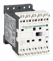
Schneider Electric LP1K06013BD3 contactor 3-pole 24VDC
| Lieske Part No. | 379419 |
|---|---|
| Mfg Part No | LP1K06013BD3 |
| EAN-Code | 3389118020856 |
| Manufacturer | Schneider Electric |
| Here only | 74,92 EUR
89,15 EUR incl. VAT
|
Further information for Schneider Electric LP1K06013BD3 contactor 3-pole 24VDC
| Additional features | |
| Application category | AC-3; AC-3e; AC-4 |
| Pole description | 3P |
| Pole contact composition | 3 S |
| [Ue] Rated operational voltage | Circuit: |
| [Ie] rated operational current | 6 A (at |
| Control circuit type | DC Standard |
| [Uc] control circuit voltage | 24 V DC |
| Motor power (kW) | 1.5 kW at 220 - 230 V AC 50/60 Hz AC-3; 2.2 kW at 380 - 415 V AC 50/60 Hz AC-3; 3 kW at 440/690 V AC 50/60 Hz AC-3; 1.5 kW at 220 - 230 V AC 50/60 Hz AC-3e; 2.2 kW at 380 - 415 V AC 50/60 Hz AC-3e; 3 kW at 440/690 V AC 50/60 Hz AC-3e; 1.5 kW at 220 - 230 V AC 50/60 Hz AC-4; 2.2 kW at 380 - 415 V AC 50/60 Hz AC-4; 3 kW at 440/690 V AC 50/60 Hz AC-4 |
| Configuration of auxiliary contacts | 1 Ö |
| [Uimp] Rated impulse voltage withstand | 8 kV |
| Over voltage category | III |
| [Ith] conventional thermal current in free air | 16 A (at 60 °C) for circuit; 10 A (at 50 °C) for signal circuit |
| [Irms] Rated making capacity | 110 A AC for power circuit conforming to IEC 60947; 110 A AC for signal circuit conforming to IEC 60947 |
| Rated breaking capacity | 110 A at 220 - 230 V corresponds to IEC 60947; 110 A at 380 - 400 V corresponds to IEC 60947; 110 A at 415 V corresponds to IEC 60947; 110 A at 440 V corresponds to IEC 60947; 80 A at 500 V corresponds to IEC 60947; 70 A at 660 - 690 V corresponds to IEC 60947 |
| [Icw] rated short-time current withstand | 90 A 50 °C - 1 s for circuit; 85 A 50 °C - 5 s for circuit; 80 A 50 °C - 10 s for circuit; 60 A 50 °C - 30 s for circuit; 45 A 50 °C - 1 min for circuit; 40 A 50 °C - 3 min for circuit; 20 A 50 °C - >= 15 min. for circuit; 80 A - 1 s for signal circuit; 90 A - 500 ms for signal circuit; 110 A - 100 ms for signal circuit |
| Associated fuse | 25 A gG at |
| Average impedance | 3 MOhm - Ith 16 A 50 Hz for circuit |
| [Ui] Rated insulation voltage | Circuit: 600 V complies with UL 508; Circuit: 690 V complies with IEC 60947-4-1; Signal circuit: 690 V complies with IEC 60947-4-1; Signal circuit: 690 V complies with IEC 60947-5-1; Signal circuit: 600 V complies with UL 508; Circuit: 600 V complies with CSA C22.2 No. 14; Signal circuit: 600 V complies with CSA C22.2 No. 14 |
| Insulation resistance | > 10 MΩ for signal circuits |
| Absorption power in W | 3 W (at 20 °C) |
| Holding power consumption in W | 3 W at 20 °C |
| Heat emission | 1,3 W |
| Control circuit voltage limits | Operation: 0.8 - 1.15 Uc (at = 0.10 Uc (at |
| Connections - terminals | Spring terminals 1 cable(s) 0.75…1.5 mm² solid; spring terminals 1 cable(s) 0.75…1.5 mm² fine-stranded without cable end; spring terminals 2 cable(s) 0.75…1.5 mm² fine-stranded without cable end |
| Max. operating rate | 3600 cyc/h |
| Coil technology | With integrated suppression unit |
| Type of auxiliary contacts | Type instantaneous 1 NC |
| Min. switching current | 5 mA for signal circuit |
| Min. switching voltage | 17 V for signal circuit |
| Mounting bracket | Plate; rail |
| Operating time | 30 - 40 ms coil excitation and NO closing; 10 ms coil de-energisation and NO opening |
| Security level rating | B10d = 1369863 cycles contactor with rated load corresponds to EN/ISO 13849-1; B10d = 20000000 cycles contactor with mechanical load corresponds to EN/ISO 13849-1 |
| Mechanical life | 10 Mcycles |
| Electrical lifetime | 1.3 Mcycles 6 A AC-3 at Ue |
| Height | 58 mm |
| Width | 45 mm |
| Depth | 57 mm |
| Product weight | 0,225 kg |
| Contractual warranty | |
| Warranty (in months) | 18 |
| Main features | |
| Product series | TeSys |
| Product or component type | Contactor |
| Device short name | LP1K |
| Application of contactor | Motor control |
| Mounting | |
| Standards | EN/IEC 60947-4-1; EN/IEC 60947-5-1; UL 60947-4-1; UL 60947-5-1; CSA C22.2 No. 60947-4-1; CSA C22.2 No. 60947-5-1; GB/T 14048.4 |
| Product certifications | CB certification; CCC; UL; CSA; EAC; CE; UKCA |
| Degree of protection (IP) | IP2x |
| Operating ambient temperature | -25…50 °C |
| Ambient temperature during storage | -50…80 °C |
| Operating altitude | 2,000 m without derating |
| Flame retardancy | V1 corresponds to UL 94; Requirement 2 corresponds to NF F 16-101; Requirement 2 corresponds to NF F 16-102 |
| Packaging units | |
| VPE 1 type | PCE |
| Number of devices per package | 1 |
| VPE 1 height | 4,800 cm |
| VPE 1 width | 6,500 cm |
| VPE 1 length | 6,200 cm |
| Packaging weight (Lbs) | 224,000 g |
| VPE 2 type | S02 |
| VPE 2 quantity | 40 |
| VPE 2 height | 15,000 cm |
| VPE 2 width | 30,000 cm |
| VPE 2 length | 40,000 cm |
| VPE 2 weight | 9,362 kg |
Applications
The contactor is designed for use in systems with medium to high operating frequency, particularly in machine controls where reliable and fast switching functions are required. The usage categories AC-3, AC-3e, and AC-4 cover various load types, from normal drives to heavy switching operations with high inrush currents. The combination of mechanical robustness and electrical reliability makes it suitable for applications in manufacturing industry, building automation, and infrastructure technology.
Functions and Equipment in Detail
The device features three closed contacts in the main current circuit (3 S) and one additional non-delayed open contact in the auxiliary contact circuit (1 Ö). This configuration enables parallel control of main and auxiliary functions, for example, for signal transmission to other components or for feedback of the switching state. The spring terminals are designed for cable cross-sections from 0.75 to 1.5 mm², suitable for both rigid and flexible conductors, with up to two flexible conductors per terminal allowed. The maximum operating rate is 3600 switching operations per hour, enabling high dynamics during operation.
Technology Explained Simply
The coil technology with integrated suppression unit reduces switching disturbances in the control circuit and prevents unwanted voltage spikes. The rated impulse voltage withstand is 8 kV, and the overvoltage category III ensures reliability during transient voltage surges. The rated insulation voltage is 690 V for both the current circuit and the signal switching circuit according to IEC 60947-4-1, ensuring safe separation between main and control circuits. The device’s heat dissipation is 1.3 W, enabling efficient cooling in enclosed switchgear.
Compatibility and Accessories
The contactor can be combined with various auxiliary switch blocks to integrate additional contacts for control or signaling purposes. Available accessories include, for example, the auxiliary switch block LA1KN223 (2 closed contacts), LA1KN403 (4 closed contacts), LA1KN023 (2 open contacts), or LA1KN113 (1 closed contact, 1 open contact). These modules extend the functionality of the contactor and allow flexible adaptation to specific requirements. Mounting is either on a plate or on a rail, enabling flexible installation in various enclosures.
Mounting and Installation
Mounting is done via rail or plate fixation, with the device dimensions being 45 mm (width) × 58 mm (height) × 57 mm (depth). The terminals are designed for connections with cables in cross-section 0.75 to 1.5 mm², with flexible conductors usable without wire end ferrules. Installation is carried out in standard enclosures, with thermal loading due to the heat dissipation of 1.3 W to be considered.
Operational Advantages
The contactor features a high mechanical life of 10 million switching cycles and an electrical life of 1.3 million cycles at 6 A AC-3. The operating time is 30–40 ms for closing and 10 ms for opening, enabling fast response to control commands. Certifications according to CSA, UL, and compliance with IEC 60947-4-1 and EN/ISO 13849-1 (safety level B10d = 1,369,863 cycles at rated load) guarantee safe and reliable operation in critical applications. The integrated suppression unit ensures disturbance-free switching in the control circuit, increasing the coil’s lifespan and the overall system reliability.

This is an offer of:
79279 Vörstetten
https://industry-electronics.com
Tel. 07666/88499-0
Fax. 07666/88499-111
Diesen Artikel finden Sie unter:
industry-electronics.com/artikel/379419

Lieske Elektronik e.K.
Reutener Str. 1079279 Vörstetten
https://industry-electronics.com
Tel. 07666/88499-0
Fax. 07666/88499-111
Diesen Artikel finden Sie unter:
industry-electronics.com/artikel/379419