
Schneider Electric LC1K09015B7 contactor 3p 24V
Industrial Material > Industrial relays and contactors > Contactors
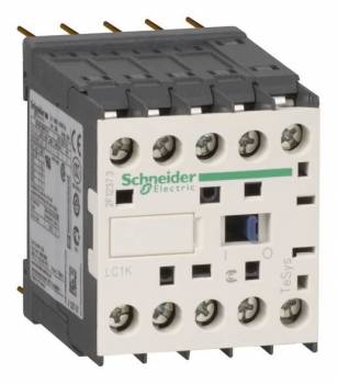
Schneider Electric LC1K09015B7 contactor 3p 24V
| Lieske Part No. | 501090 |
|---|---|
| Mfg Part No | LC1K09015B7 |
| EAN-Code | 3389110489965 |
| Manufacturer | Schneider Electric |
| Here only | 50,63 EUR
60,25 EUR incl. VAT
|
Further information for Schneider Electric LC1K09015B7 contactor 3p 24V
| Complementary | |
| Utilisation category | AC-3; AC-3e; AC-1; AC-4 |
| Poles description | 3P |
| power pole contact composition | 3 NO |
| [Ue] rated operational voltage | Power circuit: |
| [Ie] rated operational current | 9 A (at |
| Control circuit type | AC at 50/60 Hz |
| [Uc] control circuit voltage | 24 V AC 50/60 Hz |
| Motor power kW | 2.2 kW at 220...230 V AC 50/60 Hz AC-3; 4 kW at 380...415 V AC 50/60 Hz AC-3; 4 kW at 440/690 V AC 50/60 Hz AC-3; 2.2 kW at 220...230 V AC 50/60 Hz AC-3e; 4 kW at 380...415 V AC 50/60 Hz AC-3e; 4 kW at 440/690 V AC 50/60 Hz AC-3e; 2.2 kW at 220...230 V AC 50/60 Hz AC-4; 4 kW at 380...415 V AC 50/60 Hz AC-4; 4 kW at 440/690 V AC 50/60 Hz AC-4 |
| Auxiliary contact composition | 1 NC |
| [Uimp] rated impulse withstand voltage | 8 kV |
| Overvoltage category | III |
| [Ith] conventional free air thermal current | 20 A (at 60 °C) for power circuit; 10 A (at 50 °C) for signalling circuit |
| Irms rated making capacity | 110 A AC for power circuit conforming to IEC 60947; 110 A AC for signalling circuit conforming to IEC 60947 |
| Rated breaking capacity | 110 A at 220...230 V conforming to IEC 60947; 110 A at 380...400 V conforming to IEC 60947; 110 A at 415 V conforming to IEC 60947; 110 A at 440 V conforming to IEC 60947; 80 A at 500 V conforming to IEC 60947; 70 A at 660...690 V conforming to IEC 60947 |
| [Icw] rated short-time withstand current | 90 A 50 °C - 1 s for power circuit; 85 A 50 °C - 5 s for power circuit; 80 A 50 °C - 10 s for power circuit; 60 A 50 °C - 30 s for power circuit; 45 A 50 °C - 1 min for power circuit; 40 A 50 °C - 3 min for power circuit; 20 A 50 °C - >= 15 min for power circuit; 80 A - 1 s for signalling circuit; 90 A - 500 ms for signalling circuit; 110 A - 100 ms for signalling circuit |
| Associated fuse rating | 25 A gG at |
| Average impedance | 3 mOhm - Ith 20 A 50 Hz for power circuit |
| [Ui] rated insulation voltage | Power circuit: 600 V conforming to UL 508; Power circuit: 690 V conforming to IEC 60947-4-1; Signalling circuit: 690 V conforming to IEC 60947-4-1; Signalling circuit: 690 V conforming to IEC 60947-5-1; Signalling circuit: 600 V conforming to UL 508; Power circuit: 600 V conforming to CSA C22.2 No 14; Signalling circuit: 600 V conforming to CSA C22.2 No 14 |
| Insulation resistance | > 10 MOhm for signalling circuit |
| Inrush power in VA | 30 VA (at 20 °C) |
| Hold-in power consumption in VA | 4.5 VA (at 20 °C) |
| Heat dissipation | 1.3 W |
| Control circuit voltage limits | Operational: 0.8...1.15 Uc (at = 0.20 Uc (at |
| Connections - terminals | Solder pins (external diameter: 0.035 mm) |
| Maximum operating rate | 3600 cyc/h |
| Coil technology | Without built-in suppressor module |
| Auxiliary contacts type | type instantaneous 1 NC |
| Minimum switching current | 5 mA for signalling circuit |
| Minimum switching voltage | 17 V for signalling circuit |
| Mounting support | Printed circuit boards |
| Operating time | 10...20 ms coil de-energisation and NO opening; 10...20 ms coil energisation and NO closing |
| Safety reliability level | B10d = 1369863 cycles contactor with nominal load conforming to EN/ISO 13849-1; B10d = 20000000 cycles contactor with mechanical load conforming to EN/ISO 13849-1 |
| Non overlap distance | 0.5 mm |
| Mechanical durability | 10 Mcycles |
| Electrical durability | 1.3 Mcycles 9 A AC-3 at Ue |
| Height | 58 mm |
| Width | 45 mm |
| Depth | 57 mm |
| Net weight | 0.18 kg |
| Contractual warranty | |
| Warranty (in months) | 18 |
| Environment | |
| Standards | EN/IEC 60947-4-1; GB/T 14048.4; UL 60947-4-1; CSA C22.2 No 60947-4-1; JIS C8201-4-1; IEC 60335-1:Clause 30.2; IEC 60335-2-40:Annex JJ; UL 60335-2-40:Annex JJ |
| Product certifications | CB Scheme; CCC; UL; CSA; EAC; CE; UKCA |
| IP degree of protection | IP2X conforming to VDE 0106 |
| Protective treatment | TC conforming to IEC 60068; TC conforming to DIN 50016 |
| Ambient air temperature for storage | -50…80 °C |
| Operating altitude | 2000 m without derating |
| Flame retardance | V1 conforming to UL 94; Requirement 2 conforming to NF F 16-101; Requirement 2 conforming to NF F 16-102 |
| Logistical informations | |
| Country of origin | FR |
| Main | |
| Range | TeSys |
| Product or component type | Contactor |
| Device short name | LC1K |
| Device application | Control |
| Contactor application | Resistive load; Motor control |
| Packing Units | |
| Unit Type of Package 1 | PCE |
| Number of Units in Package 1 | 1 |
| Package 1 Height | 4.900 cm |
| Package 1 Width | 6.300 cm |
| Package 1 Length | 7.000 cm |
| Package 1 Weight | 206.000 g |
Applications
The contactor is approved for categories AC-1, AC-3, AC-3e, and AC-4, with AC-3 being the typical application for motor drives. At an operating voltage of 380–415 V AC and an operating frequency of 50/60 Hz, the rated operational power is 4 kW and the rated operational current is 9 A. The motor power may vary depending on the voltage range, with 2.2 kW achievable at 220–230 V AC and 4 kW at 440/690 V AC. The application therefore covers both small and medium motors in industrial plants.
Functions and Equipment in Detail
The device includes an auxiliary contact in normally open (NO) configuration, which can be used for additional control or signaling tasks. The coil has an inrush power of 30 VA and a holding power consumption of 4.5 VA at 20 °C, ensuring efficient power supply. The heat dissipation is 1.3 W, limiting thermal load during operation. The control circuit voltage limits range from 0.8 to 1.15 times the nominal voltage, enabling reliable operation during voltage fluctuations. The terminals are designed as solder pins, with an outer diameter of 0.035 mm.
Technology Explained Simply
The rated surge voltage withstand is 8 kV, and the overvoltage category is III, providing high safety against transient voltage spikes. The rated insulation voltage is 690 V for both the power circuit and the signal circuit, in accordance with IEC 60947-4-1 and IEC 60947-5-1. The insulation resistance is specified as > 10 MΩ for the signal circuit, ensuring high electrical insulation. The rated breaking capacity is 110 A at 220–230 V and 380–415 V, with 70 A achievable at 660–690 V. The rated short-time current withstand is defined for various durations, with values for the power circuit ranging from 90 A (1 s) to 20 A (≥15 min).
Compatibility and Accessories
The contactor can be combined with various accessories to extend its functionality. These include auxiliary switch blocks such as LA1KN04 (4 NO), LA1KN02 (2 NO), LA1KN20 (2 NC), or LA1KN40 (4 NC). For delayed functions, modules such as LA2KT2U (delayed 30 s) or LA2KT2E (delayed pickup 1–30 s) are available. Additionally, overvoltage limiters such as LA4KE1B (12–42 V) or labeling plates such as LA9D90 can be used to enhance application safety and identification.
Mounting and Installation
Mounting is done on printed circuit boards, with the device dimensions (45 × 58 × 57 mm) enabling compact placement. The maximum operating rate is 3600 switching operations per hour, sufficient for dynamic applications. The operating time is 10–20 ms for coil de-energization and NO opening, as well as for coil energization and NO closing. The mechanical life is 10 million switching cycles, and the electrical life is 1.3 million cycles at 9 A AC-3. The safety class corresponds to EN/ISO 13849-1 with a B10d value of 1,369,863 cycles at rated load and 20,000,000 cycles at mechanical load.
Advantages in Operation
The contactor offers high reliability due to the specified life expectancy and robust construction. The low heat dissipation and efficient coil power reduce energy consumption. Compatibility with various accessories allows flexible adaptation to different requirements. Certifications according to CSA and UL, as well as compliance with standards IEC 60947 and UL 508, ensure safety and suitability for international markets. The simple interface for electronic devices such as PLCs facilitates integration into modern control systems.

This is an offer of:
79279 Vörstetten
https://industry-electronics.com
Tel. 07666/88499-0
Fax. 07666/88499-111
Diesen Artikel finden Sie unter:
industry-electronics.com/artikel/501090

Lieske Elektronik e.K.
Reutener Str. 1079279 Vörstetten
https://industry-electronics.com
Tel. 07666/88499-0
Fax. 07666/88499-111
Diesen Artikel finden Sie unter:
industry-electronics.com/artikel/501090