
Schneider Electric LC1D1506N7 contactor 3p 150A
Industrial Material > Industrial relays and contactors > Contactors
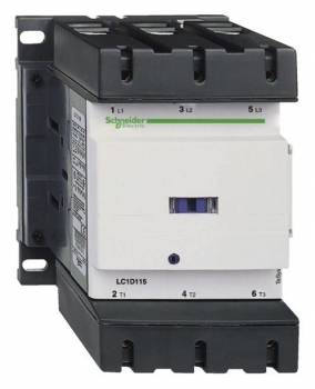
Schneider Electric LC1D1506N7 contactor 3p 150A
| Lieske Part No. | 494448 |
|---|---|
| Mfg Part No | LC1D1506N7 |
| EAN-Code | 3389110528725 |
| Manufacturer | Schneider Electric |
| Here only | 891,22 EUR
1.060,55 EUR incl. VAT
|
Further information for Schneider Electric LC1D1506N7 contactor 3p 150A
| Complementary | |
| Motor power kW | 40 kW at 220/230 V AC 50/60 Hz (AC-3); 75 kW at 380/400 V AC 50/60 Hz (AC-3); 80 kW at 415/440 V AC 50/60 Hz (AC-3); 90 kW at 500 V AC 50/60 Hz (AC-3); 100 kW at 660/690 V AC 50/60 Hz (AC-3); 75 kW at 1000 V AC 50/60 Hz (AC-3); 40 kW at 220/230 V AC 50/60 Hz (AC-3e); 75 kW at 380/400 V AC 50/60 Hz (AC-3e); 80 kW at 415/440 V AC 50/60 Hz (AC-3e); 90 kW at 500 V AC 50/60 Hz (AC-3e); 100 kW at 660/690 V AC 50/60 Hz (AC-3e); 75 kW at 1000 V AC 50/60 Hz (AC-3e); 22 kW at 400 V AC 50/60 Hz (AC-4) |
| Motor power hp | 40 hp at 200/208 V AC 50/60 Hz for 3 phases motors; 50 hp at 230/240 V AC 50/60 Hz for 3 phases motors; 100 hp at 460/480 V AC 50/60 Hz for 3 phases motors; 125 hp at 575/600 V AC 50/60 Hz for 3 phases motors |
| Compatibility code | LC1D |
| Pole contact composition | 3 NO |
| Protective cover | With |
| [Ith] conventional free air thermal current | 200 A (at 60 °C) for power circuit |
| Irms rated making capacity | 140 A AC for signalling circuit conforming to IEC 60947-5-1; 250 A DC for signalling circuit conforming to IEC 60947-5-1; 1660 A at 440 V for power circuit conforming to IEC 60947 |
| Rated breaking capacity | 1400 A at 440 V for power circuit conforming to IEC 60947 |
| [Icw] rated short-time withstand current | 250 A 40 °C - 10 min for power circuit; 580 A 40 °C - 1 min for power circuit; 1200 A 40 °C - 10 s for power circuit; 1400 A 40 °C - 1 s for power circuit; 100 A - 1 s for signalling circuit; 120 A - 500 ms for signalling circuit; 140 A - 100 ms for signalling circuit |
| Associated fuse rating | 10 A gG for signalling circuit conforming to IEC 60947-5-1; 315 A gG at |
| Average impedance | 0.6 mOhm - Ith 200 A 50 Hz for power circuit |
| Power dissipation per pole | 24 W AC-1; 13.5 W AC-3; 13.5 W AC-3e |
| [Ui] rated insulation voltage | Power circuit: 600 V CSA certified; Power circuit: 600 V UL certified; Power circuit: 1000 V conforming to IEC 60947-4-1; Signalling circuit: 690 V conforming to IEC 60947-1; Signalling circuit: 600 V CSA certified; Signalling circuit: 600 V UL certified |
| Overvoltage category | III |
| Pollution degree | 3 |
| [Uimp] rated impulse withstand voltage | 8 kV conforming to IEC 60947 |
| Safety reliability level | B10d = 684932 cycles contactor with nominal load conforming to EN/ISO 13849-1; B10d = 10000000 cycles contactor with mechanical load conforming to EN/ISO 13849-1 |
| Mechanical durability | 8 Mcycles |
| Electrical durability | 0.85 Mcycles 150 A AC-3 at Ue |
| Control circuit type | AC at 50/60 Hz |
| Coil technology | Built-in bidirectional peak limiting diode suppressor |
| Control circuit voltage limits | 0.3...0.5 Uc (-40…70 °C):drop-out AC 50/60 Hz; 0.8...1.15 Uc (-40…55 °C):operational AC 50/60 Hz; 1...1.15 Uc (55…70 °C):operational AC 50/60 Hz |
| Inrush power in VA | 280…350 VA 60 Hz cos phi 0.9 (at 20 °C); 280…350 VA 50 Hz cos phi 0.9 (at 20 °C) |
| Hold-in power consumption in VA | 2…18 VA 60 Hz cos phi 0.9 (at 20 °C); 2…18 VA 50 Hz cos phi 0.9 (at 20 °C) |
| Heat dissipation | 3…4.5 W at 50/60 Hz |
| Operating time | 20...35 ms closing; 40...75 ms opening |
| Maximum operating rate | 1200 cyc/h at 60 °C |
| Connections - terminals | Control circuit: lugs-ring terminals - external diameter: 8 mm; Power circuit: lugs-ring terminals - external diameter: 25 mm; Power circuit: bars 1 - busbar cross section: 5 x 25 mm |
| Tightening torque | Control circuit: 1.2 N.m - on lugs-ring terminals - with screwdriver flat Ø 6 mm M3.5; Control circuit: 1.2 N.m - on lugs-ring terminals - with screwdriver Philips No 2 M3.5; Power circuit: 12 N.m - on lugs-ring terminals hexagonal screw head 13 mm M8; Power circuit: 12 N.m - on bars hexagonal screw head 13 mm M8; Control circuit: 1.2 N.m - on lugs-ring terminals - with screwdriver pozidriv No 2 M3.5 |
| Auxiliary contact composition | 1 NO + 1 NC |
| Auxiliary contacts type | type mechanically linked 1 NO + 1 NC conforming to IEC 60947-5-1; type mirror contact 1 NC conforming to IEC 60947-4-1 |
| Signalling circuit frequency | 25...400 Hz |
| Minimum switching voltage | 17 V for signalling circuit |
| Minimum switching current | 5 mA for signalling circuit |
| Insulation resistance | > 10 MOhm for signalling circuit |
| Non-overlap time | 1.5 ms on de-energisation between NC and NO contact; 1.5 ms on energisation between NC and NO contact |
| Mounting support | Rail; Plate |
| Contractual warranty | |
| Warranty (in months) | 18 |
| Environment | |
| Standards | CSA C22.2 No 14; EN 60947-4-1; IEC 60947-4-1; IEC 60335-1:Clause 30.2; IEC 60335-2-40:Annex JJ; UL 60335-2-40:Annex JJ; UL 60947-4-1; CSA C22.2 No 60947-4-1; JIS C8201-4-1 |
| Product certifications | UL; CCC; CSA; CE; UKCA; Marine; EAC |
| IP degree of protection | IP20 front face conforming to IEC 60529 |
| Protective treatment | TH conforming to IEC 60068-2-30 |
| Climatic withstand | conforming to IACS E10 exposure to damp heat |
| Permissible ambient air temperature around the device | -40…60 °C; 60…70 °C with derating |
| Operating altitude | 0...3000 m |
| Fire resistance | 850 °C conforming to IEC 60695-2-1 |
| Flame retardance | V1 conforming to UL 94 |
| Mechanical robustness | Vibrations contactor open (2 Gn, 5...300 Hz) ; Vibrations contactor closed (4 Gn, 5...300 Hz) ; Shocks contactor closed (15 Gn for 11 ms) ; Shocks contactor open (6 Gn for 11 ms) |
| Height | 158 mm |
| Width | 120 mm |
| Depth | 136 mm |
| Net weight | 2.5 kg |
| Logistical informations | |
| Country of origin | CZ |
| Main | |
| Range | TeSys |
| Range of product | TeSys Deca Advanced |
| Product or component type | Contactor |
| Device short name | LC1D |
| Contactor application | Motor control; Resistive load |
| Utilisation category | AC-3; AC-3e; AC-1; AC-4 |
| Poles description | 3P |
| [Ue] rated operational voltage | Power circuit: |
| [Ie] rated operational current | 200 A (at |
| [Uc] control circuit voltage | 415 V AC 50/60 Hz |
| Packing Units | |
| Unit Type of Package 1 | PCE |
| Number of Units in Package 1 | 1 |
| Package 1 Height | 16.800 cm |
| Package 1 Width | 20.800 cm |
| Package 1 Length | 18.500 cm |
| Package 1 Weight | 2.130 kg |
| Unit Type of Package 2 | S03 |
| Number of Units in Package 2 | 2 |
| Package 2 Height | 30 cm |
| Package 2 Width | 30 cm |
| Package 2 Length | 40 cm |
| Package 2 Weight | 4.680 kg |
| Unit Type of Package 3 | P06 |
| Number of Units in Package 3 | 16 |
| Package 3 Height | 75.000 cm |
| Package 3 Width | 80.000 cm |
| Package 3 Length | 60.000 cm |
| Package 3 Weight | 45.440 kg |
Applications
The contactor is designed for various usage categories, including AC-1, AC-3, AC-3e, and AC-4. These categories cover operation with resistive loads, motor drives with normal and heavy loads, and frequent switching. Category AC-3e refers to operation with motors under high starting current load, typical for drives in material handling or pump applications. The mechanical service life is 8 million switching cycles, while the electrical service life at 150 A and AC-3 operation is 850,000 switching cycles. This makes the device suitable for applications requiring high operational durability.
Functions and Equipment in Detail
The contactor features 3 closed contacts in the main current circuit and additional auxiliary contacts configured as 1 closed + 1 open. These auxiliary contacts enable integration into control and safety circuits, for example, for feedback of switching status or for interlocking operating equipment. The contacts are mechanically coupled and feature mirror contacts, enhancing reliability in safety-critical applications. The current circuit terminals are designed for ring cable lugs with an outer diameter of 25 mm, with mounting screws having a hexagonal head of 13 mm diameter and M8 thread. Torque specifications are provided to ensure a secure and durable connection.
Technology Explained Simply
The contactor coil is designed for an operating voltage of 415 V AC and operates at frequencies of 50/60 Hz. The pickup power is between 280 and 350 VA, while the holding power consumption is between 2 and 18 VA. The operating time is 20 to 35 ms for closing and 40 to 75 ms for opening. The maximum operating rate is 1200 switching cycles per hour at an ambient temperature of 60 °C. The heat dissipation of the device is between 3 and 4.5 W at 50/60 Hz, describing the thermal load during operation. The rated insulation voltage is 1000 V for the current circuit according to IEC 60947-4-1 and 690 V for the control circuit according to IEC 60947-1. Overvoltage category III and pollution degree 3 indicate suitability for industrial environments with increased electrical stress and contamination risk.
Compatibility and Accessories
The contactor is compatible with various accessories, including auxiliary switch blocks such as the LAD8N116 (1S+1O un-delayed side-mounted) or the LADN206 (2S un-delayed front-mounted). Time blocks such as the LADT46 (1S1O delayed pickup) can be used to extend control functions. For motor protection, the relay LR9D5369 (90–150 A, Class 10) is suitable. The use of spreaders such as the GV7AC03 enables mounting in control panels. Compatibility with these components expands the application possibilities of the contactor in complex control systems.
Mounting and Installation
Mounting is done via the designated connection terminals, with the current circuit terminals designed for ring cable lugs with a 25 mm outer diameter. The mounting screws in the current circuit require a tightening torque of 12 Nm. The control circuit terminals are designed for ring cable lugs with an 8 mm outer diameter, with a tightening torque of 1.2 Nm. Installation is carried out in control panels or enclosures, with the device dimensions being 120 mm (width) × 158 mm (height) × 136 mm (depth). The weight is 2.5 kg. Installation must be performed by qualified personnel to ensure the safety and functionality of the device.
Operational Advantages
The contactor offers high operational durability with a mechanical service life of 8 million cycles and an electrical service life of 850,000 cycles under AC-3 operation. The integrated bidirectional amplitude limiter diode protects the coil from voltage spikes, increasing reliability. The use of Everlink and spring terminals ensures a secure and long-lasting current connection. The mechanical coupling of contacts and the use of mirror contacts enhance safety in critical applications. Certifications according to UL, CSA, CCC, DNV, GL, BV, RINA, GOST, and LROS (Lloyds Register of Shipping) confirm suitability for international applications, including marine environments.
Certifications
The device meets the requirements of standards IEC 60947-4-1, IEC 60947-5-1, and EN/ISO 13849-1. Certifications according to UL, CSA, CCC, DNV, GL, BV, RINA, GOST, and LROS (Lloyds Register of Shipping) confirm suitability for international and marine applications. Overvoltage category III and pollution degree 3 indicate suitability for industrial environments with increased stress.

This is an offer of:
79279 Vörstetten
https://industry-electronics.com
Tel. 07666/88499-0
Fax. 07666/88499-111
Diesen Artikel finden Sie unter:
industry-electronics.com/artikel/494448

Lieske Elektronik e.K.
Reutener Str. 1079279 Vörstetten
https://industry-electronics.com
Tel. 07666/88499-0
Fax. 07666/88499-111
Diesen Artikel finden Sie unter:
industry-electronics.com/artikel/494448