
Schneider Electric LC1D09B7 Contactor 3p 1S+1O 24V
Industrial Material > Industrial relays and contactors > Contactors
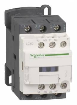
Schneider Electric LC1D09B7 Contactor 3p 1S+1O 24V
| Lieske Part No. | 251292 |
|---|---|
| Mfg Part No | LC1D09B7 |
| EAN-Code | 3389110348675 |
| Manufacturer | Schneider Electric |
| Here only | 51,21 EUR
60,94 EUR incl. VAT
|
Further information for Schneider Electric LC1D09B7 Contactor 3p 1S+1O 24V
| Complementary | |
| Motor power kW | 2.2 kW at 220/230 V AC 50/60 Hz (AC-3); 4 kW at 380/400 V AC 50/60 Hz (AC-3); 4 kW at 415/440 V AC 50/60 Hz (AC-3); 5.5 kW at 500 V AC 50/60 Hz (AC-3); 5.5 kW at 660/690 V AC 50/60 Hz (AC-3); 2.2 kW at 220/230 V AC 50/60 Hz (AC-3e); 4 kW at 380/400 V AC 50/60 Hz (AC-3e); 4 kW at 415/440 V AC 50/60 Hz (AC-3e); 5.5 kW at 500 V AC 50/60 Hz (AC-3e); 5.5 kW at 660/690 V AC 50/60 Hz (AC-3e); 2.2 kW at 400 V AC 50/60 Hz (AC-4) |
| Motor power hp | 1 hp at 230/240 V AC 50/60 Hz for 1 phase motors; 2 hp at 200/208 V AC 50/60 Hz for 3 phases motors; 2 hp at 230/240 V AC 50/60 Hz for 3 phases motors; 5 hp at 460/480 V AC 50/60 Hz for 3 phases motors; 7.5 hp at 575/600 V AC 50/60 Hz for 3 phases motors; 0.33 hp at 115 V AC 50/60 Hz for 1 phase motors |
| Compatibility code | LC1D |
| Pole contact composition | 3 NO |
| Protective cover | With |
| [Ith] conventional free air thermal current | 25 A (at 60 °C) for power circuit; 10 A (at 60 °C) for signalling circuit |
| Irms rated making capacity | 250 A at 440 V for power circuit conforming to IEC 60947; 140 A AC for signalling circuit conforming to IEC 60947-5-1; 250 A DC for signalling circuit conforming to IEC 60947-5-1 |
| Rated breaking capacity | 250 A at 440 V for power circuit conforming to IEC 60947 |
| [Icw] rated short-time withstand current | 105 A 40 °C - 10 s for power circuit; 210 A 40 °C - 1 s for power circuit; 30 A 40 °C - 10 min for power circuit; 61 A 40 °C - 1 min for power circuit; 100 A - 1 s for signalling circuit; 120 A - 500 ms for signalling circuit; 140 A - 100 ms for signalling circuit |
| Associated fuse rating | 10 A gG for signalling circuit conforming to IEC 60947-5-1; 25 A gG at |
| Average impedance | 2.5 mOhm - Ith 25 A 50 Hz for power circuit |
| Power dissipation per pole | 1.56 W AC-1; 0.2 W AC-3; 0.2 W AC-3e |
| [Ui] rated insulation voltage | Power circuit: 690 V conforming to IEC 60947-4-1; Power circuit: 600 V CSA certified; Power circuit: 600 V UL certified; Signalling circuit: 690 V conforming to IEC 60947-1; Signalling circuit: 600 V CSA certified; Signalling circuit: 600 V UL certified |
| Overvoltage category | III |
| Pollution degree | 3 |
| [Uimp] rated impulse withstand voltage | 6 kV conforming to IEC 60947 |
| Safety reliability level | B10d = 1369863 cycles contactor with nominal load conforming to EN/ISO 13849-1; B10d = 20000000 cycles contactor with mechanical load conforming to EN/ISO 13849-1 |
| Mechanical durability | 15 Mcycles |
| Electrical durability | 0.6 Mcycles 25 A AC-1 at Ue |
| Control circuit type | AC at 50/60 Hz standard |
| Coil technology | Without built-in suppressor module |
| Control circuit voltage limits | 0.3...0.6 Uc (-40…70 °C):drop-out AC 50/60 Hz; 0.8...1.1 Uc (-40…60 °C):operational AC 50 Hz; 0.85...1.1 Uc (-40…60 °C):operational AC 60 Hz; 1...1.1 Uc (60…70 °C):operational AC 50/60 Hz |
| Inrush power in VA | 70 VA 60 Hz cos phi 0.75 (at 20 °C); 70 VA 50 Hz cos phi 0.75 (at 20 °C) |
| Hold-in power consumption in VA | 7.5 VA 60 Hz cos phi 0.3 (at 20 °C); 7 VA 50 Hz cos phi 0.3 (at 20 °C) |
| Heat dissipation | 2…3 W at 50/60 Hz |
| Operating time | 12...22 ms closing; 4...19 ms opening |
| Maximum operating rate | 3600 cyc/h at 60 °C |
| Auxiliary contact composition | 1 NO + 1 NC |
| Auxiliary contacts type | type mechanically linked 1 NO + 1 NC conforming to IEC 60947-5-1; type mirror contact 1 NC conforming to IEC 60947-4-1 |
| Signalling circuit frequency | 25...400 Hz |
| Minimum switching voltage | 17 V for signalling circuit |
| Minimum switching current | 5 mA for signalling circuit |
| Insulation resistance | > 10 MOhm for signalling circuit |
| Non-overlap time | 1.5 ms on de-energisation between NC and NO contact; 1.5 ms on energisation between NC and NO contact |
| Mounting support | Rail; Plate |
| Contractual warranty | |
| Warranty (in months) | 18 |
| Environment | |
| Standards | CSA C22.2 No 14; EN 60947-4-1; EN 60947-5-1; IEC 60947-4-1; IEC 60947-5-1; UL 60947-4-1; IEC 60335-1:Clause 30.2; IEC 60335-2-40:Annex JJ; UL 60335-2-40:Annex JJ; CSA C22.2 No 60947-4-1 |
| Product certifications | UL; CCC; CSA; Marine; UKCA; EAC; CB Scheme |
| IP degree of protection | IP20 front face conforming to IEC 60529 |
| Protective treatment | TH conforming to IEC 60068-2-30 |
| Climatic withstand | conforming to IACS E10 exposure to damp heat; conforming to IEC 60947-1 Annex Q category D exposure to damp heat |
| Permissible ambient air temperature around the device | -40…60 °C; 60…70 °C with derating |
| Operating altitude | 0...3000 m |
| Fire resistance | 850 °C conforming to IEC 60695-2-1 |
| Flame retardance | V1 conforming to UL 94 |
| Mechanical robustness | Vibrations contactor open (2 Gn, 5...300 Hz) ; Vibrations contactor closed (4 Gn, 5...300 Hz) ; Shocks contactor open (10 Gn for 11 ms) ; Shocks contactor closed (15 Gn for 11 ms) |
| Height | 77 mm |
| Width | 45 mm |
| Depth | 86 mm |
| Net weight | 0.32 kg |
| Logistical informations | |
| Country of origin | FR |
| Main | |
| Range of product | TeSys Deca Advanced |
| Product or component type | Contactor |
| Device short name | LC1D |
| Contactor application | Resistive load; Motor control |
| Utilisation category | AC-3; AC-3e; AC-1; AC-4 |
| Poles description | 3P |
| [Ue] rated operational voltage | Power circuit: |
| [Ie] rated operational current | 9 A (at |
| [Uc] control circuit voltage | 24 V AC 50/60 Hz |
| Packing Units | |
| Unit Type of Package 1 | PCE |
| Number of Units in Package 1 | 1 |
| Package 1 Height | 5.000 cm |
| Package 1 Width | 9.200 cm |
| Package 1 Length | 11.200 cm |
| Package 1 Weight | 345.000 g |
| Unit Type of Package 2 | S02 |
| Number of Units in Package 2 | 20 |
| Package 2 Height | 15.000 cm |
| Package 2 Width | 30.000 cm |
| Package 2 Length | 40.000 cm |
| Package 2 Weight | 7.193 kg |
| Unit Type of Package 3 | P06 |
| Number of Units in Package 3 | 320 |
| Package 3 Height | 75.000 cm |
| Package 3 Width | 60.000 cm |
| Package 3 Length | 80.000 cm |
| Package 3 Weight | 126.688 kg |
Applications
The contactor is primarily designed for motor control, especially for drives with a power up to 4 kW at 400 V AC (AC-3). It is also suitable for resistive loads and can be used in installations with various operating categories, including category AC-4, which applies to high mechanical stresses such as starting or braking operations. Approvals according to UL, CSA, GL, DNV, BV, CCC, GOST, RINA, and LROS (Lloyds Register of Shipping) make it suitable for international and marine applications. The overvoltage category III and pollution degree 3 indicate use in environments with increased electrical stress and risk of contamination.
Functions and Equipment in Detail
The device features a safety cover enabling secure access to the contacts. The contacts are mechanically coupled and include mirror contacts, increasing reliability in safety applications. Electrical connection is achieved via Everlink technology and spring clamps, ensuring quick and secure installation. The rated short-time withstand current is 105 A at 40 °C for 10 seconds in the circuit, ensuring stability during short-term overloads. The rated breaking capacity is 250 A at 440 V, highlighting the ability to interrupt short-circuit currents.
Technology Explained Simply
The coil is supplied with 24 V AC, with the operating voltage required to be between 0.8 and 1.1 times the nominal voltage to ensure reliable operation. The pickup power is 70 VA at 50 Hz and 60 Hz, while the holding power consumption is 7 VA (50 Hz) or 7.5 VA (60 Hz). The heat dissipation is 2 to 3 W at 50/60 Hz, describing the thermal load of the device during operation. The mechanical life is 15 million switching cycles, and the electrical life is 0.6 million cycles at 25 A AC-1. The rated impulse voltage withstand is 6 kV, protecting the device against transient voltage surges. The power loss per pole is 1.56 W at AC-1 and 0.2 W at AC-3 and AC-3e, reflecting the device’s efficiency under various load conditions.
Compatibility and Accessories
The contactor is equipped with compatibility code LC1D, enabling use with accessories such as auxiliary switch blocks (e.g. LADN20, LADN02, LADN04, LAD8N11, LAD8N02, LADN31), time blocks (e.g. LADT2, LADT0, LADR2, LADR0, LAD-R4), interlocking blocks (e.g. LAD6K10B), wiring modules (e.g. LAD4RCE), varistors (e.g. LAD-4VE), and motor protection circuit breakers (e.g. GV2LE14, LRD14). These modules can be added to extend functions such as time delay, interlocking, or motor protection. The device is also suitable for use in three-phase busbar systems such as GV2G445.
Mounting and Installation
Mounting is done via screw connection, with Everlink technology and spring clamps ensuring a secure and long-lasting electrical connection. Dimensions are 45 mm (width) × 77 mm (height) × 86 mm (depth), and the net weight is 0.32 kg. Installation is in standard control panels or enclosures, with designated connection points and mechanical stability of the connection ensuring reliable operation even under industrial conditions. The duty cycle is 12, indicating the maximum operating duration under continuous load.
Advantages in Operation
The contactor offers high reliability through mechanically coupled contacts and mirror contacts, which are critical for safety applications. The long life of 15 million mechanical and 0.6 million electrical switching cycles ensures long-term operational safety. The use of Everlink technology and spring clamps reduces installation time and improves contact quality. Approvals according to international standards enable worldwide use, particularly in marine and industrial environments. The integrated auxiliary contacts simplify control of complex systems without requiring additional components to be installed.

This is an offer of:
79279 Vörstetten
https://industry-electronics.com
Tel. 07666/88499-0
Fax. 07666/88499-111
Diesen Artikel finden Sie unter:
industry-electronics.com/artikel/251292

Lieske Elektronik e.K.
Reutener Str. 1079279 Vörstetten
https://industry-electronics.com
Tel. 07666/88499-0
Fax. 07666/88499-111
Diesen Artikel finden Sie unter:
industry-electronics.com/artikel/251292