
Schneider Electric GV2L16 motor protection switch 3p 14A
Industrial Material > Control devices / Pilot devices > Motor protection switch
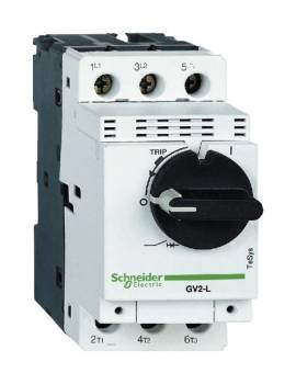
Schneider Electric GV2L16 motor protection switch 3p 14A
| Lieske Part No. | 359344 |
|---|---|
| Mfg Part No | GV2L16 |
| EAN-Code | 3389110213287 |
| Manufacturer | Schneider Electric |
| Here only | 111,63 EUR
132,84 EUR incl. VAT
|
Further information for Schneider Electric GV2L16 motor protection switch 3p 14A
| Complementary | |
| Poles description | 3P |
| Network type | AC |
| Utilisation category | Category A conforming to IEC 60947-2; AC-3 conforming to IEC 60947-4-1; AC-3e conforming to IEC 60947-4-1 |
| Network frequency | 50/60 Hz conforming to IEC 60947-2 |
| Motor power kW | 5.5 kW at 400/415 V AC 50/60 Hz; 7.5 kW at 500 V AC 50/60 Hz; 9 kW at 690 V AC 50/60 Hz; 11 kW at 690 V AC 50/60 Hz |
| Breaking capacity | 100 kA Icu at 230/240 V AC 50/60 Hz conforming to IEC 60947-2; 50 kA Icu at 400/415 V AC 50/60 Hz conforming to IEC 60947-2; 20 kA Icu at 440 V AC 50/60 Hz conforming to IEC 60947-2; 10 kA Icu at 500 V AC 50/60 Hz conforming to IEC 60947-2; 4 kA Icu at 690 V AC 50/60 Hz conforming to IEC 60947-2 |
| [Ics] rated service short-circuit breaking capacity | 100 % at 230/240 V AC 50/60 Hz conforming to IEC 60947-2; 50 % at 400/415 V AC 50/60 Hz conforming to IEC 60947-2; 75 % at 440 V AC 50/60 Hz conforming to IEC 60947-2; 75 % at 500 V AC 50/60 Hz conforming to IEC 60947-2; 100 % at 690 V AC 50/60 Hz conforming to IEC 60947-2 |
| Control type | Rotary handle |
| [In] rated current | 14 A |
| Magnetic tripping current | 253.4 A |
| [Ith] conventional free air thermal current | 14 A conforming to IEC 60947-2 |
| [Ue] rated operational voltage | 690 V AC 50/60 Hz conforming to IEC 60947-2 |
| [Ui] rated insulation voltage | 690 V AC 50/60 Hz conforming to IEC 60947-2 |
| [Uimp] rated impulse withstand voltage | 6 kV conforming to IEC 60947-2 |
| Suitability for isolation | Yes conforming to IEC 60947-1 |
| Power dissipation per pole | 1.8 W |
| Mechanical durability | 100000 cycles |
| Electrical durability | 100000 cycles for AC-3 at 415 V In; 100000 cycles for AC-3e at 415 V In |
| Rated duty | Uninterrupted conforming to IEC 60947-4-1 |
| Connections - terminals | Power circuit: screw clamp terminal 2 cable(s) 1…6 mm² - solid; Power circuit: screw clamp terminal 2 cable(s) 1.5…6 mm² - flexible without cable end; Power circuit: screw clamp terminal 2 cable(s) 1…4 mm² - flexible with cable end |
| Tightening torque | 1.7 N.m - on screw clamp terminal |
| Fixing mode | 35 mm symmetrical DIN rail: clipped; Panel: screwed (with 2 x M4 screws) |
| Mounting position | Horizontal; Vertical |
| Width | 45 mm |
| Height | 89 mm |
| Depth | 97 mm |
| Net weight | 0.33 kg |
| Colour | Dark grey |
| Contractual warranty | |
| Warranty (in months) | 18 |
| Environment | |
| Standards | EN/IEC 60947-2; EN/IEC 60947-4-1; UL 60947-4-1; CSA C22.2 No 60947-4-1; IEC/EN 60335-2-40:Annex JJ |
| Product certifications | CB Scheme; CE; UKCA; CCC; cULus; EAC; LROS (Lloyds register of shipping); BV; RINA; DNV-GL |
| IK degree of protection | IK04 |
| IP degree of protection | IP20 conforming to IEC 60529 |
| Climatic withstand | conforming to IACS E10 |
| Ambient air temperature for storage | -40…80 °C |
| Fire resistance | 960 °C conforming to IEC 60695-2-11 |
| Ambient air temperature for operation | -20…60 °C |
| Mechanical robustness | Shocks: 30 Gn for 11 ms; Vibrations: 5 Gn, 5...150 Hz |
| Logistical informations | |
| Country of origin | FR |
| Main | |
| Range | TeSys Deca |
| Product name | TeSys GV2 |
| Product or component type | Motor circuit breaker |
| Device short name | GV2L |
| Device application | Motor protection |
| Trip unit technology | Magnetic |
| Packing Units | |
| Unit Type of Package 1 | PCE |
| Number of Units in Package 1 | 1 |
| Package 1 Height | 5.000 cm |
| Package 1 Width | 9.500 cm |
| Package 1 Length | 10.200 cm |
| Package 1 Weight | 321.000 g |
| Unit Type of Package 2 | S02 |
| Number of Units in Package 2 | 20 |
| Package 2 Height | 15.000 cm |
| Package 2 Width | 30.000 cm |
| Package 2 Length | 40.000 cm |
| Package 2 Weight | 6.675 kg |
| Unit Type of Package 3 | P06 |
| Number of Units in Package 3 | 320 |
| Package 3 Height | 75.000 cm |
| Package 3 Width | 60.000 cm |
| Package 3 Length | 80.000 cm |
| Package 3 Weight | 114.272 kg |
Applications
The GV2L16 is designed for use in industrial applications, particularly in systems with start motors and stop motors. It protects motors with a power rating of 5.5 kW at 400/415 V AC, 7.5 kW at 500 V AC, and 9 kW and 11 kW at 690 V AC. The usage category includes Category A according to IEC 60947-2 as well as AC-3 and AC-3e according to IEC 60947-4-1, making it suitable for use in applications with high mechanical and electrical loads.
Functions and Equipment in Detail
The switch offers thermal and magnetic tripping, with the magnetic tripping current set at 253.4 A. The rated current is 14 A, with the conventional thermal current in free air also being 14 A. The power loss per pole is 1.8 W. The mechanical life is 100,000 cycles, as is the electrical life for AC-3 and AC-3e at 415 V In. The rated power is uninterrupted according to IEC 60947-4-1.
Technology Explained Simply
Tripping is achieved through a combination of thermal and magnetic protection functions. The thermal tripping responds to sustained overloads, while the magnetic tripping activates during sudden short-circuits or high current surges. The operating rated voltage of 690 V AC allows use in high-voltage installations. The rated insulation voltage is also 690 V AC, and the rated impulse voltage withstand is 6 kV. Suitability for insulation is according to IEC 60947-1.
Compatibility and Accessories
The switch can be combined with various accessories, including connection blocks such as GV1G09, undervoltage release units such as GVAU207, auxiliary switches such as GVAE20, motor protection relays such as LRD16 and LRD21, load current releases such as GVAS055 and GVAS026, and rotary drive sets such as GV2APN02 and GV2APN01. Additionally, three-phase busbar systems such as GV2G345, GV2G354, GV2G254, GV2G445, and GV2G454 are available. The shaft GVAPK11 with a length of 250 mm is also compatible.
Mounting and Installation
Mounting is either on a 35 mm symmetrical DIN rail via clamping or on a panel using screw fastening with two M4 screws. The mounting position can be horizontal or vertical. Dimensions are 45 mm width, 89 mm height, and 97 mm depth. The product weight is 0.33 kg. The degree of protection is IP20 according to IEC 60529, providing protection against finger contact and solid foreign objects, but not against water. The IK04 protection rating safeguards against mechanical impacts. The ambient temperature during operation ranges from -20 °C to 60 °C, and during storage from -40 °C to 80 °C. The fire resistance is 960 °C according to IEC 60695-2-11.
Operational Advantages
The GV2L16 offers high reliability due to its robust construction and long service life. The simple operation via the rotary handle and compact design facilitate installation and maintenance. The high breaking capacity at various voltages (e.g., 100 kA Icu at 230/240 V AC) ensures safe operation even in demanding environments. Certifications according to CB regulation, CE, UKCA, CCC, cULus, EAC, LROS, BV, RINA, and DNV-GL confirm compliance with international safety and quality standards.

This is an offer of:
79279 Vörstetten
https://industry-electronics.com
Tel. 07666/88499-0
Fax. 07666/88499-111
Diesen Artikel finden Sie unter:
industry-electronics.com/artikel/359344

Lieske Elektronik e.K.
Reutener Str. 1079279 Vörstetten
https://industry-electronics.com
Tel. 07666/88499-0
Fax. 07666/88499-111
Diesen Artikel finden Sie unter:
industry-electronics.com/artikel/359344