
HAGER VH60BV1 - small volta HWV 5x12PLE IP30 equipped
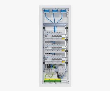
HAGER VH60BV1 - small volta HWV 5x12PLE IP30 equipped
| Lieske Part No. | 2121879 |
|---|---|
| Mfg Part No | VH60BV1 |
| EAN-Code | 3250619926018 |
| Manufacturer | Hager |
| Here only | 1.780,87 EUR
2.119,24 EUR incl. VAT
|
Further information for HAGER VH60BV1 - small volta HWV 5x12PLE IP30 equipped
| General | |
| Mounting method | Hollow wall |
| Number of phases | 3 |
| Protection | Other |
| Number of groups behind earth leakage switch | 6 |
| Number of earth leakage circuit breakers | 3 |
| Number of earth leakage switches 30 mA | 3 |
| Number of earth leakage switches 300 mA | 0 |
| Material housing | Plastic |
| Degree of protection (IP) | IP30 |
| Height | 880.5 mm |
| Width | 348 mm |
| Width in number of modular spacings | 12 |
| Depth | 94.5 mm |
| Built-in depth | 89 mm |
| Built-in height | 845 mm |
| Built-in width | 314 mm |
| Colour | White |
| Connection type | Other |
| Number of rows | 5 |
| RAL-number | 9010 |
| Release characteristic | B |
| Type of closure | Other |
| Type of cover | Door |
| With socket outlet | |
| With bell transformer | |
| Over voltage protection | |
| Extension possible | |
| With transparent cover | |
| Lockable | |
| Suitable for data | |
| With N-disconnect slide | |
Equipped and wired with:
- 3 x residual current circuit breakers, 4-pole, 40A
- 15 x LS switches, 1-pole, 16A
- 1 x LS switch, 3-pole, 20A
- 1 x surge arrester type 2
- 1 main line branch terminal
- including main current wiring.

This is an offer of:
79279 Vörstetten
https://industry-electronics.com
Tel. 07666/88499-0
Fax. 07666/88499-111
Diesen Artikel finden Sie unter:
industry-electronics.com/artikel/2121879

Lieske Elektronik e.K.
Reutener Str. 1079279 Vörstetten
https://industry-electronics.com
Tel. 07666/88499-0
Fax. 07666/88499-111
Diesen Artikel finden Sie unter:
industry-electronics.com/artikel/2121879