
Moeller 280915 P5-125/V/SVB/HI10 main switch intermediate section
Industrial Material > Control devices / Pilot devices > Cam switch / power switch
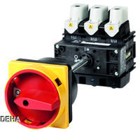
Moeller 280915 P5-125/V/SVB/HI10 main switch intermediate section
| Lieske Part No. | 244000 |
|---|---|
| Mfg Part No | 280915 |
| EAN-Code | 4015082809157 |
| Manufacturer | Eaton |
| Here only | 365,78 EUR
435,28 EUR incl. VAT
|
Further information for Moeller 280915 P5-125/V/SVB/HI10 main switch intermediate section
| General | |
| Degree of protection | IP65 Front |
| Rated continuous current | 125 A |
| Rated operating power | 45 kW |
| Operating voltage | 400 V |
| Frequency | 50 - 60 Hz |
| Number of poles | 3 way |
| Construction type | rear mounting |
| Function | EMERGENCY STOP function |
| Locking | lockable in position 0 (off) |
| Standards | IEC/EN 60947, VDE 0660, IEC/EN 60204, CSA, UL |
| Manufacturer | Eaton |
| Assortment | main switch, maintenance switch |
| Scope of delivery | auxiliary contact or neutral conductor installed by customer |
Applications
The switch is intended for use in industrial installations, machine controls, and electrical distributions, particularly where secure and manual power disconnection is required. It is commonly used in production plants, material handling systems, machine tools, and other installations where emergency shutdown is necessary during operation or maintenance. The locking in position 0 (Off) enhances safety during maintenance, as the switch cannot be accidentally turned on.
Functions and Equipment in Detail
The switch is designed as an intermediate build and allows integration into existing control systems. The emergency stop function is realized by locking in position 0 (Off), meaning the switch can only be locked in this position. The red rotary handle with yellow locking ring serves as a visual indicator for emergency shutdown and meets industrial safety requirements. The rated continuous current is 125 A, making it suitable for medium to high loads. The rated operational power at AC-23A, 50–60 Hz, and 400 V is 45 kW, confirming its performance for typical industrial applications.
Technology Explained Simply
The switch complies with standards IEC/EN 60947, VDE 0660, IEC/EN 60204, CSA, and UL, which regulate electrical safety and functionality in industrial installations. The IP65 protection rating means the front side of the switch is dust-tight and protected against splashing water, making it suitable for environments with increased humidity or mechanical stress. The rear-mounting design allows flexible installation in enclosures. The rated continuous current of 125 A and operational power of 45 kW at 400 V and 50–60 Hz define the maximum electrical loads the switch can safely handle.
Compatibility and Accessories
Various accessories are available for this switch to extend its functionality. These include additional front plates such as ZFS63-T0 (French) or ZFS62-P3 for labeling and identification. Locking extensions like ZVV-T0 or shaft extensions like ZAV-P3 allow for adjustable mounting. Knob handles such as KNB-RT-P3 (red) or SVB-SW-P3 (black) offer alternative operating options. Additional items include coupling drives (DE-T0), terminal covers (H-P1), insulating material housings (CI-K4-P3-63), and mounting brackets (AB-CI-K4/5). For integration into safety systems, key actuators (S-SOND-KMS(*)-T0) and cylinder lock locks (SVA(*)-SOND-SA(*)-T3) are available. The installation of auxiliary contacts or switchable neutral conductors is performed by the customer.
Installation and Mounting
The switch is mounted rearward into enclosures. Installation is done by securing it to the rear of the housing using the designated mounting points. Electrical connections are made via terminals on the rear side. The locking in position 0 (Off) can be enhanced with additional locking elements such as shaft extensions or cylinder lock locks. Installation requires compliance with electrical standards and correct sizing of conductors according to the rated continuous current of 125 A.
Operational Advantages
The switch provides clear visual identification of the emergency stop function via the red rotary handle and yellow locking ring. Locking in position 0 (Off) increases safety during maintenance. The IP65 protection rating allows use in harsh environments. The high rated continuous current of 125 A and operational power of 45 kW at 400 V make it suitable for a wide range of industrial applications. Compatibility with various accessories allows flexible adaptation to specific requirements.
Standards and Regulations
The switch complies with standards IEC/EN 60947, VDE 0660, IEC/EN 60204, CSA, and UL. It is classified as a switch disconnector according to IEC/EN 60947-3, fulfilling requirements for electrical safety and function as a disconnecting device. These standards ensure reliability and safety in industrial use.
Additional Information
The installation of auxiliary contacts or switchable neutral conductors is performed by the customer. Electrical connections are made via terminals on the rear side of the device. The IP65 protection rating applies to the front side of the switch; the rear side is not protected.
Rated Values
The rated continuous current is 125 A. The rated operational power at AC-23A, 50–60 Hz, and 400 V is 45 kW. The front side protection rating is IP65. The construction type is rear mounting. The emergency stop function can be locked in position 0 (Off). The switch is 3-pole and complies with standards IEC/EN 60947, VDE 0660, IEC/EN 60204, CSA, and UL.
Accessories
Various accessories are available for this switch, including additional front plates (ZFS63-T0, ZFS62-P3), knob handles (KNB-RT-P3, SVB-SW-P3), locking extensions (ZVV-T0), shaft extensions (ZAV-P3), mounting brackets (AB-CI-K4/5), coupling drives (DE-T0), terminal covers (H-P1), insulating material housings (CI-K4-P3-63), key actuators (S-SOND-KMS(*)-T0), cylinder lock locks (SVA(*)-SOND-SA(*)-T3), and standard parts for main switches (V/EA/SVB-T0, V/EA/SVB-SW-T0). The installation of auxiliary contacts or switchable neutral conductors is performed by the customer.
Accessories
Various accessories are available for this switch, including additional front plates (ZFS63-T0, ZFS62-P3), knob handles (KNB-RT-P3, SVB-SW-P3), locking extensions (ZVV-T0), shaft extensions (ZAV-P3), mounting brackets (AB-CI-K4/5), coupling drives (DE-T0), terminal covers (H-P1), insulating material housings (CI-K4-P3-63), key actuators (S-SOND-KMS(*)-T0), cylinder lock locks (SVA(*)-SOND-SA(*)-T3), and standard parts for main switches (V/EA/SVB-T0, V/EA/SVB-SW-T0). The installation of auxiliary contacts or switchable neutral conductors is performed by the customer.

This is an offer of:
79279 Vörstetten
https://industry-electronics.com
Tel. 07666/88499-0
Fax. 07666/88499-111
Diesen Artikel finden Sie unter:
industry-electronics.com/artikel/244000

Lieske Elektronik e.K.
Reutener Str. 1079279 Vörstetten
https://industry-electronics.com
Tel. 07666/88499-0
Fax. 07666/88499-111
Diesen Artikel finden Sie unter:
industry-electronics.com/artikel/244000