
DEHN 927971 BCO CL2 BD HF 5 combo surge arrester 1 pair cable
Energy > Surge Protection
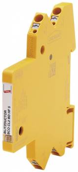
DEHN 927971 BCO CL2 BD HF 5 combo surge arrester 1 pair cable
| Lieske Part No. | 1780566 |
|---|---|
| Mfg Part No | 927971 |
| EAN-Code | 4013364411999 |
| Manufacturer | DEHN |
| Here only | 129,67 EUR
154,31 EUR incl. VAT
|
Further information for DEHN 927971 BCO CL2 BD HF 5 combo surge arrester 1 pair cable
| General | |
| Mounting width | 6 mm |
| Connection system | Push-in |
| Degree of protection | for 1 pair cable |
| Application range | earth potential-free high-frequency bus systems, symmetric interfaces |
| Extended technical data | |
| Max. discharge current (8/20 µs) [1/2 - PG], [1+2 - PG] (Imax) | 20 kA |
| Discharge current (8/20 µs) [1/2 - PG], [1+2 - PG] | 10 kA (10x) |
| Voltage protection level line-PG at 1 kV/μs C3 after being subjected to Imax (UP) | ≤ 600 V |
| Technical data | |
| SPD class | L |
| Impulse category | D1, C1, C2, C3, B2 |
| Nominal voltage (UN) | 5 V |
| Max. continuous operating voltage DC (UC) | 8.5 V |
| Max. continuous operating a.c. voltage (UC) | 6.0 V |
| Nominal current at 70 °C (IL) | 0.75 A |
| D1 Total lightning impulse current (10/350 µs) (Iimp) | 3 kA |
| D1 Lightning impulse current (10/350 µs) per line (Iimp) | 1.5 kA |
| C2 Total nominal discharge current (8/20 µs) (In) | 10 kA |
| C2 Nominal discharge current (8/20 µs) per line (In) | 5 kA |
| Voltage protection level line-line for In C2 (UP) | ≤ 42 V |
| Voltage protection level line-PG for In C2 (UP) | ≤ 600 V |
| Voltage protection level line-line for In C1 (UP) | ≤ 42 V |
| Voltage protection level line-PG for In C1 (UP) | ≤ 600 V |
| Voltage protection level line-line at 1 kV/µs C3 (UP) | ≤ 15 V |
| Voltage protection level line-PG at 1 kV/µs C3 (Up) | ≤ 600 V |
| Series resistance per line | 1 Ohm |
| Cut-off frequency line-line (fG) | 100 MHz |
| Capacitance line-line (C) | ≤ 21 pF |
| Capacitance line-PG (C) | ≤ 15 pF |
| Operating temperature range (TU) | -40 °C ... +80 °C |
| Operating state / fault indication | green / red |
| Degree of protection | IP 20 |
| For mounting on | 35 mm DIN rails acc. to EN 60715 |
| Connection (input / output) | push-in / push-in |
| Cross-sectional area, solid | 0.2-2.5 mm2 |
| Cross-sectional area, flexible | 0.2-2.5 mm2 |
| Earthing via | 35 mm DIN rails acc. to EN 60715 |
| Enclosure material | polyamide PA 6.6 |
| Colour | yellow |
| Test standards | IEC 61643-21 / EN 61643-21 |
| Approvals | UL 497B, CSA, ATEX, IECEx, CCC, SIL |
| SIL classification | up to SIL3 *) |
| ATEX approvals | TÜV 20 ATEX 8527 X: II 3G Ex ec IIC T4 Gc |
| IECEx approvals | IECEx TUR 20.0063X: Ex ec IIC T4 Gc |
| China Compulsory Certification | CCC no. 2021312304001192 |
| Test values according to UL 497b | |
| Type (SPD classification) | BCO CL2 BD HF 5 |
| Strike voltage Line to Ground 100 V/s min. | 10,3 V |
| Strike voltage Line to Ground 100 V/s max. | 11,8 V |
| Strike voltage Line to Line 100 V/s min. | 72 V |
| Strike voltage Line to Line 100 V/s max. | 108 V |
Combination surge arrester for earth potential-free systems
The arrester is designed for use in earth potential-free high-frequency bus systems, such as those found in industrial automation or communication networks. It protects the connected conductors against overvoltages caused by lightning discharges or electrical disturbances in the network. The design as a combination surge arrester means it is suitable for both high-voltage impulse diversion and protection against low-frequency disturbances.
Push-in connection technology and status indicator
The push-in technology allows for quick and secure connection of conductors without additional tools. Conductors are simply inserted into the designated connection openings, creating a reliable electrical connection. The integrated status indicator provides visual feedback on the operating condition. It indicates whether the arrester is still functional or if damage has occurred, simplifying maintenance and diagnostics during operation.
Protection of 1 twisted pair
The arrester is designed for the protection of a single twisted pair, making it particularly suitable for applications where only one pair of conductors needs protection. This includes, for example, data lines in fieldbus systems such as Profibus, Modbus, or similar protocols transmitted over symmetrical lines. The design ensures effective noise suppression and overvoltage diversion without impairing the signal integrity of high-frequency data transmission.
Applications
The DEHN BCO CL2 BD HF 5 is used in industrial control systems, automation plants, and building automation, where earth potential-free, high-frequency bus systems are employed. It is suitable for use in enclosures, distribution boxes, and other enclosed installations where a compact design and secure mounting are required. Its specific design supports use in symmetrical interfaces, which are common in many modern communication and control systems.
Technology explained simply
The arrester operates on the principle of overvoltage diversion, where overvoltages entering through the connected conductors are diverted via a diversion resistor or varistor structure. This protects sensitive downstream electronic components from damage. The push-in technology ensures a mechanically stable and electrically reliable connection, while the status indicator monitors operation. The width of 6 mm allows dense mounting on standard 35 mm rails, optimizing space utilization in enclosures.
Compatibility and accessories
The arrester is designed for use in earth potential-free high-frequency systems and can be combined with other DEHN surge protection devices in an enclosure to create a comprehensive protection concept. It is not specifically designed for a particular bus type, but for general earth potential-free, symmetrical interfaces, enabling broad applicability. Use in combination with other protective measures, such as earthing systems or additional filters, is possible if system requirements demand it.
Mounting and installation
Mounting is done on a standard 35 mm rail, with the 6 mm width allowing dense arrangement of multiple arresters. The push-in connections require no tools for connecting conductors, speeding up installation. The status indicator is directly visible on the device, allowing the condition to be checked without additional measuring instruments. Installation is carried out in enclosed switchgear, with environmental conditions meeting the requirements of the respective standards.
Operational advantages
The DEHN BCO CL2 BD HF 5 offers a compact design that saves space in enclosures and easy installation via push-in technology. The integrated status indicator enables quick diagnosis and maintenance. The specific design for earth potential-free, high-frequency systems ensures effective protection without impairing signal transmission. These features support its use in industrial applications where reliability and ease of maintenance are important.

This is an offer of:
79279 Vörstetten
https://industry-electronics.com
Tel. 07666/88499-0
Fax. 07666/88499-111
Diesen Artikel finden Sie unter:
industry-electronics.com/artikel/1780566

Lieske Elektronik e.K.
Reutener Str. 1079279 Vörstetten
https://industry-electronics.com
Tel. 07666/88499-0
Fax. 07666/88499-111
Diesen Artikel finden Sie unter:
industry-electronics.com/artikel/1780566