
DEHN 900360 DVA CSP 3P 100 FM combination arrester
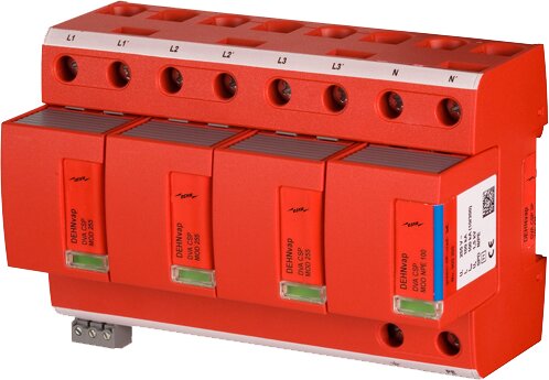
DEHN 900360 DVA CSP 3P 100 FM combination arrester
| Lieske Part No. | 1570628 |
|---|---|
| Mfg Part No | 900360 |
| EAN-Code | 4013364111332 |
| Manufacturer | DEHN |
| Here only | 1.962,04 EUR
2.334,83 EUR incl. VAT
|
Further information for DEHN 900360 DVA CSP 3P 100 FM combination arrester
| General | |
| SPD according to EN 61643-11 / IEC 61643-11 | type 1 + type 2 / class I + class II |
| Energy coordination with terminal equipment (≤ 10 m) | type 1 + type 2 + type 3 |
| Nominal voltage (a.c.) (UN) | 230 / 240 V (50 / 60 Hz) |
| Max. continuous operating voltage (a.c.) [L-N]/[N-PE] (UC) | 264 V (50 / 60 Hz) |
| Max. continuous operating voltage (a.c.) [N-PE] (UC (N-PE)) | 255 V (50 / 60 Hz) |
| Lightning impulse current (10/350 µs) [L1+L2+L3+N-PE] (Itotal) | 100 kA |
| Lightning impulse current (10/350 µs) [L-N]/[N-PE] (Iimp) | 25 / 100 kA |
| Nominal discharge current (8/20 µs) (In) | 25 / 100 kA |
| Specific energy [L1+L2+L3+N-PE] (W/R) | 2.50 MJ/ohms |
| Specific energy [L-N]/[N-PE] (W/R) | 156.25 kJ/ohms / 2.50 MJ/ohms |
| Voltage protection level [L-N]/[N-PE] (UP) | ≤ 1.5 kV / ≤ 1.5 kV |
| Follow current extinguishing capability [L-N]/[N-PE] (Ifi) | 25 kArms / 100 Arms |
| Follow current limitation / Selectivity | no tripping of a 20 A gG fuse up to 25 kArms (prosp.) |
| Response time (tA) | ≤ 100 ns |
| Max. backup fuse (L) up to IK = 25 kArms | 315 A gG |
| Max. backup fuse (L) up to IK 25 kArms | 200 A gG |
| Max. backup fuse (L-L') | 125 A gG |
| Temporary overvoltage (TOV) [L-N] (UT) – Characteristic | 440 V / 120 min. – withstand |
| Temporary overvoltage (TOV) [N-PE] (UT) - Characteristic | 1200 V / 200 ms – withstand |
| Additional abnormal voltage test: 485 V AC / 50 Hz for 24 h | withstand |
| Operating temperature range [parallel]/[series] (TU) | -40°C...+80°C / -40°C...+60°C |
| Operating state / fault indication | green / red |
| Number of ports | 1 |
| Cross-sectional area (L1, L1', L2, L2', L3, L3', N, N', PE, ) (min.) | 10 mm2 solid / flexible |
| Cross-sectional area (L1, L2, L3, N, PE) (max.) | 50 mm2 stranded / 35 mm2 flexible |
| Cross-sectional area (L1', L2', L3', N', ) (max.) | 35 mm2 stranded / 25 mm2 flexible |
| For mounting on | 35 mm DIN rails acc. to EN 60715 |
| Enclosure material | thermoplastic, red, UL 94 V-0 |
| Place of installation | indoor installation |
| Degree of protection | IP 20 |
| Capacity | 8 Standard DIN module, DIN 43880 |
| Approvals | KEMA |
| Type of remote signalling contact | changeover contact |
| Switching capacity (a.c.) | 250 V / 0.5 A |
| Switching capacity (d.c.) | 250 V / 0.1 A; 125 V / 0.2 A; 75 V / 0.5 A |
| Cross-sectional area for remote signalling terminals | max. 1.5 mm2 solid / flexible |
Applications
This surge arrester is primarily intended for use in mobile communication installations, where high system availability and reliability are required. It protects the power supply against transient overvoltages caused by lightning strikes or network disturbances. The device is installed indoors on a 35 mm DIN rail in accordance with EN 60715 and is designed for integration into existing power supply systems.
Functions and Equipment in Detail
The DVA CSP 3P 100 FM features an integrated optical status indicator that visually signals the operating state: green for normal operation, red for fault. Additionally, a remote signaling contact (changeover contact) is integrated, enabling status notification in case of arrester failure. The switching capacity is 250 V/0.5 A for alternating current and 250 V/0.1 A, 125 V/0.2 A, and 75 V/0.5 A for direct current. The maximum cross-section for the FM terminals is limited to 1.5 mm², either solid or stranded wire.
Technology Explained Simply
The arrester provides a lightning impulse current rating of 100 kA (10/350 µs) across all conductors (L1+L2+L3+N-PE) and a nominal discharge current of 25/100 kA (8/20 µs). The protection level is ≤ 1.5 kV for phase-to-neutral and neutral-to-protective earth connections. The follow current interruption capability is 25 kAeff for L-N and 100 Aeff for N-PE. The RADAX-Flow technology ensures selective follow current limitation, preventing a 20 A gG fuse from tripping even at short-circuit currents up to 25 kAeff. The response time is ≤ 100 ns, ensuring rapid reaction to overvoltages. The maximum upstream fuse rating is 315 A gG at IK = 25 kAeff and 200 A gG at IK > 25 kAeff. For phase-to-phase connections, a maximum upstream fuse of 125 A gG is specified.
Compatibility and Accessories
The arrester is designed for use in TT and TN-S systems and is suitable for protection arrangements in mobile communication installations. The specific energy is 2.50 MJ/Ohm for all conductors and 156.25 kJ/Ohm or 2.50 MJ/Ohm for individual connections. The TOV voltage (Temporary Overvoltage) is 440 V for 120 minutes on L-N and 1200 V for 200 ms on N-PE. An additional voltage test at 485 V AC/50 Hz for 24 hours is performed as a dielectric strength test.
Mounting and Installation
Mounting is done on a 35 mm DIN rail in accordance with EN 60715. The housing is made of thermoplastic material in red, certified to UL 94 V-0. The mounting dimensions correspond to 8 TE according to DIN 43880. The operating temperature ranges are -40°C to +80°C in parallel operation and -40°C to +60°C in through operation. The protection rating is IP 20, providing protection against finger contact and solid foreign objects, but not against water or dust.
Operational Advantages
Thanks to the integrated RADAX-Flow technology, high system availability is achieved, as the arrester operates selectively even at high short-circuit currents. The simple module locking allows for replacement of the protection module without tools. The optical indicator and remote signaling contact support system maintenance and monitoring. The connection cross-sections range from a minimum of 10 mm² (solid or stranded) to a maximum of 50 mm² (stranded) or 35 mm² (solid) for main conductors, and 35 mm² (stranded) or 25 mm² (solid) for auxiliary conductors.

This is an offer of:
79279 Vörstetten
https://industry-electronics.com
Tel. 07666/88499-0
Fax. 07666/88499-111
Diesen Artikel finden Sie unter:
industry-electronics.com/artikel/1570628

Lieske Elektronik e.K.
Reutener Str. 1079279 Vörstetten
https://industry-electronics.com
Tel. 07666/88499-0
Fax. 07666/88499-111
Diesen Artikel finden Sie unter:
industry-electronics.com/artikel/1570628