
Chauvin Arnoux P01295143A test lead X+H 5 m 2 pcs
Measurement > Measuring Accessories > Test leads
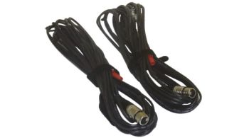
Chauvin Arnoux P01295143A test lead X+H 5 m 2 pcs
| Lieske Part No. | 895809 |
|---|---|
| Mfg Part No | P01295143A |
| EAN-Code | 3663653003315 |
| Manufacturer | Chauvin Arnoux |
| Here only | 941,90 EUR
1.120,86 EUR incl. VAT
|
Further information for Chauvin Arnoux P01295143A test lead X+H 5 m 2 pcs
| Eigenschaften | |
| Dimensions / weight | 270 x 250 x 130 mm / 3,4 kg |
Applications
These test leads are intended for use with digital turns ratio testers from the DTR series, particularly models DTR 8500 and DTR 8510. They are used during maintenance, commissioning, or inspections to measure the turns ratio, winding polarity, and excitation current. Testing is performed in accordance with IEEE Std C57.12.90, the standard for transformer and transformer testing. The leads support fully automatic measurement without manual settings or calibration.
Functions and Features in Detail
The cables are shielded to minimize interference from electric fields and ensure measurement accuracy. At the ends, crocodile clips with color coding are attached, enabling quick and unambiguous assignment of connections. The color coding supports correct connection to the H and X terminals of the transformer. The length of 4.6 m provides sufficient flexibility during installation and positioning of the test device in the field.
Technology Explained Simply
The shielded wiring protects measurement signals from electromagnetic interference, which can occur during testing of high-voltage transformers. The crocodile clips ensure a secure electrical contact, even on rough surfaces or slightly contaminated connection points. Color coding reduces the risk of incorrect connections, which is particularly important for complex transformers. The length of 4.6 m is approximately 15 feet and suitable for typical field applications.
Compatibility and Accessories
The test leads are specifically designed for DTR 8500 and DTR 8510 test devices. They are intended as a replacement or supplement for the cables included with the device. Compatible accessories available in the range include crocodile clips CAT IV-1000 V 15 A red+black and a transport bag. These items can be used additionally to enhance safety and mobility during testing.
Installation and Mounting
Installation is performed by connecting the crocodile clips to the corresponding terminals of the transformer — “H” on the primary side and “X” on the secondary side. The cables are designed to ensure a secure and stable connection. The length of 4.6 m allows flexible positioning of the test device without affecting the measurement. The shielded wiring ensures reliable signal transmission.
Operational Advantages
Using these replacement test leads ensures high measurement accuracy and reliability. The shielded wiring and color-coded crocodile clips reduce sources of error. The length of 4.6 m provides sufficient flexibility for field operations. Compatibility with DTR 8500 and DTR 8510 test devices enables seamless integration into existing testing processes. The leads are robust and designed for use in industrial environments.
Protection Rating
The test leads themselves are not assigned a protection rating. The protection classes IP 40 (cover open) and IP 53 (cover closed) refer to the test device, not the leads. However, the cables are designed for industrial environments and made from materials that withstand mechanical stress.
Connection and Interface
The leads feature XLR connectors that plug directly into the corresponding sockets on the test device. The crocodile clips at the ends allow direct connection to transformer terminals. Color coding supports correct assignment of connections.
Safety
The test leads are designed for use with test devices compliant with EN 61010-2-030. Testing is performed in the low-voltage range, ensuring operator safety. The crocodile clips are designed for secure connections, even under high currents and voltages during testing.
Software and Communication
The test leads themselves are not software or communication components. Communication with the test device occurs via the XLR connectors. Data transmission and evaluation are handled by the integrated DataView® software, supplied with the device. The test leads are part of the measurement setup but do not participate in data communication.
Battery and Power Supply
The test leads require no separate power supply. Power is supplied by the test device, which operates on 6 rechargeable NiMH-AA batteries (2500 mAh). The leads are passive and transmit only measurement signals.
Memory and Autonomy
The test leads have no internal memory. Measurement results are stored in the test device, which can store up to 9,801 tests. The device’s autonomy is up to 500 TT/TP measurements, with a low-battery warning displayed. The leads do not affect autonomy, as they consume no power.
Display and User Interface
The test device features an alphanumeric LCD display with 4 lines of 20 characters each. The display is readable day and night thanks to backlighting. The test leads themselves have no display. Results are shown on the test device, including turns ratio, excitation current, winding polarity, and percentage deviation from nominal values.
Available Languages
Language selection is performed within the test device. Available languages include French, English, Spanish, Italian, German, and Portuguese. The test leads themselves are language-independent.
Excitation Signal
The excitation signal is generated by the test device. In TT/TP mode, the maximum voltage is 30 Vrms; in TC mode, an automatically adjusted level of 0 to 2 A and 0.1 to 5 Vrms is used. The test leads transmit the signal passively and do not affect excitation.
Accessories and Alternatives
Compatible accessories include crocodile clips CAT IV-1000 V 15 A red+black and a transport bag. These can be used additionally to enhance safety and mobility during testing. The crocodile clips are designed for secure connections, and the transport bag provides protection and ease of transport.
Practical Use
The test leads are designed for use in industrial electrical engineering, for maintenance and servicing of transformers and transformers. They are used in workshops, during commissioning, and during inspections. The length of 4.6 m allows flexible positioning of the test device, even with larger transformers. The shielded wiring ensures reliable measurement, even in electromagnetically noisy environments.

This is an offer of:
79279 Vörstetten
https://industry-electronics.com
Tel. 07666/88499-0
Fax. 07666/88499-111
Diesen Artikel finden Sie unter:
industry-electronics.com/artikel/895809

Lieske Elektronik e.K.
Reutener Str. 1079279 Vörstetten
https://industry-electronics.com
Tel. 07666/88499-0
Fax. 07666/88499-111
Diesen Artikel finden Sie unter:
industry-electronics.com/artikel/895809