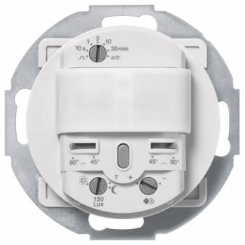
Further information for Berker 80262161 KNX motion sensor module 1.1 m
General
Mounting method
Flush mounted (plaster)
Material
Other
Surface protection
Untreated
Max. transmission range sideways
8 m
Max. transmission range frontally
12 m
Detection angle vertical
7
Detection angle horizontal
180
Number of channels
3
Switching power
0
Min. switch-on time
10 s
Max. duty cycle
30 min
Bus system KNX
Bus system KNX radio
Bus system radio frequent
Bus system LON
Bus system Powernet
Radio frequent bidirectional
Transparent
Bus connection included
Substation input
Creep-under protection
Operation mode switch
Animal zone
Staircase monitoring
Response value luminosity adjustable
Teach-function for response value luminosity
Switch-off delay self-learning
KNX motion detector module 1.1 m with integrated bus coupler, round support ring Rx KNX system description The KNX system is a flexible, upwards compatible installation bus system (formerly EIB = European Installation Bus) for use in building system technology. It is specially tailored to special requirements with regard to comfort, the option of flexible use of space, the combination of central and decentralized control, the intelligent linking of trades and systems, communication options, environmental compatibility, the minimization of energy and running costs as well as the functions of display, reporting, operating, monitoring and detecting. Thanks to its decentralized structure, it enables building-specific operational management in residential and commercial buildings, regardless of the size of the system. The usability of commercially available circuit distributors and installation boxes is particularly advantageous. All bus participants are connected via a bus cable that complies with the KNX guidelines (Konnex Association) (e.g. JY(St)Y 2x2x0.8). Since the bus line can be laid directly next to high-voltage lines according to DIN VDE 0100, the cable routing is greatly simplified. Compared to public telecommunications systems, the bus system with all its components is to be treated like a high-voltage system. As with high-voltage installations, the cable routing can be linear, star-shaped or tree-shaped. A combination of the different cable routings is generally permitted. The wiring is done using two-wire technology, with the wires colored red (for '+') and black (for '-') representing the preferred wires. The wires colored white and yellow serve as reserves. The participants are supplied with the bus voltage (protective extra-low voltage SELV 30 V DC) via the bus line. At the same time, it is used to transmit the information that is exchanged between the bus participants. A terminating resistor is not required for the bus line. The smallest unit in the KNX system is a participant. Each participant consists of a user module (AM) and a bus coupling unit (BA). AM and BA are connected to each other via the user interface (AST). Up to 64 participants can be connected to one line. Twelve lines can be connected to one another using line couplers and thus combined into one area. Up to 15 of these areas can be connected to one another using area couplers. Planning, parameterization, commissioning and diagnostics are carried out using the ETS (EIB tool software). The system documentation is also created using the ETS. During planning, each participant is assigned a unique physical address. This is made up of the number of the area, the line and the participant within the line. During commissioning, this physical address is first loaded into the BA.For this purpose, the PC is connected to the bus via a data interface (USB) at any point in the system. All BAs of a KNX system are programmed with the assigned applications from the manufacturer's database using the physical addresses. Each BA contains an EEPROM in which the physical address and the application are stored. In this way, the KNX system is protected against data loss in the event of a power failure. The following conditions apply when installing the KNX system: - The total length of all cables laid in a bus line must not exceed 1000 m! - The maximum length between two bus devices is 700 m! - The maximum cable length between the power supply (including choke) and each bus device must not exceed 350 m! - To avoid EMC interference caused by overvoltage, ensure that the bus cable does not form a closed loop at any point in the system! - The project planning and parameterization as well as the installation